
TM 5-3895-356-14&P
and on to flange (2) being carefull not to disturb the
(5 and lock washers (6) in trunnions and torque to 132 in.
assembled, internal parts. See Fig. 144. Install hex
lbs.
nuts (3) and lock washers (4) and torque to 450 in. lbs.
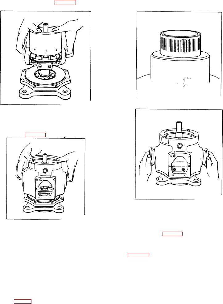
Figure 145.
Inspecting trunnions
Figure 143.
Position rotating group
20. Inspect the trunnions (7). Small nicks or burrs can
be removed with 500 grit emery cloth. If galling or
scoring can be felt with the fingernail, the trunnion should
be discarded. See Fig. 145.
Figure 146.
Installing trunnions
22. Inspect cam lever bolt holes being certain they are
clean and dry. Install lever assembly (35) including
Figure 144.
dowel pin (36). Apply Loctite, Grade D, to allen head
Positions pump housing
cap screw threads (28), install screws and torque screws
to 1040 in. lbs. See Fig. 147.
21. Assemble new trunnion thrust bearings (27) and
gaskets (24) on trunnions (7). Insert a large screw driver
23. Inspect pump cover (9) bronze face for signs of
through the cam lever opening in the housing and
cavitation, excess wear, contamination or other damage.
between the cam assembly and the back face of the
See Fig. 148.
flange. A slight downward pressure on the screw driver
will lift the cam assembly into position to allow insertion
If circular wear patterns cannot be felt with a fingernail
of the trunnion.
and if there are no nicks, scratches or other surface
blemishes, one or two passes across 500 grit emery
Do not drive or torce trunnions into position. If the
paper on a lap surface will put the bronze face in like-
trunnions do not slide easily into place, rotate the
new condition. If scratches or the wear pattern can be
trunnions slowly back and forth while repositioning the
felt with a fingernail, use 500 grit emery as described
cam with the screw driver until the trunnions seat
above
and
continue
to
make
passes
properly. See Fig.146. Install eight hex bolts
100