
TM 5-3895-356-14&P
500 R P.M. input equals 204 gal/min. For example, with
D. Manual Control
a 600 R P M input speed, again from an electric drill
press or other source, the pump flow indicator should
Place distributor control lever in "Fill from supply
read 244 gal/min. (600/500 X 204 = 244). Replace
source" position (Fig. 69). Engage P T.O., set micro
indicators as necessary.
control to 100 G P M. flow, open supply source valve
and draw into the distributor approximately 100 gallons of
testing oil (Relatively clean used engine oil of SAE grade
B. Final Inspection
40 would be satisfactory) Close supply source valve,
Check oil level in hydraulic reservoir and add if
reduce pump flow to zero and disconnect fill hose at
necessary With distributor circulating in tank at 200 G
distributor Replace fill line cap and locate distributor
P.M., and hydraulic oil at operating temperature, check to
levers and spray bar ends for circulate in bar position
insure suction on filter is not in red zone. If suction
(Figure 33) Engage P T O and set micro control to 100
indicates in red zone, replace filter element Place
G.P M At this time, check for leaks m spray bar and lines
distributor control levers m "draw back" position (Fig. 71
from asphalt pump. Tighten fittings and valves where
) to draw all material back into tank Pump test oil back
necessary. Note, a small amount of leakage may occur
into supply source as instructed in Fig. 73 for "pump off"
from ball joints until hot asphaltic material has circulated
procedure Open dram valves after pump-off by placing
through spray bar After eliminating leaks, place
drain valve lever m rear most position This will remove
distributor control levers in draw-back position (Fig. 71 )
most residual test oil from distributor system. Finally,
so as to draw all oil back into the tank
drain burner fuel from supply tank by opening petcock on
bottom of tank
III. DRY RUN CHECK OUT
A. Operation of Distributor Controls
First with bar turned up and ends latched in place,
move distributor levers to circulate in tank position (Fig.
72). Next, let fifth wheel down and with P T.O. engaged
drive distributor forward at a steady speed of 300 ft/min.
While driving at this steady speed, adjust micro control
until pump flow rate is 100 gal/min Hold micro control in
this location by turning lock tube up against under side of
micro control knob After locking knob in place, increase
distributor ground speed to 450 ft/min Pump flow rate
should be 150 gal/min. Next, decrease speed to 200
ft/min and flow rate should drop to 75 gal/min. If these
ground speeds and flow rates do not correspond, check
for air leaks in suction line between hydraulic reservoir
and pump suction port Tighten fittings as necessary Air
in hydraulic oil will cause it to appear milky If this is not a
problem, check ground speed indicator dial, 1000 R P M.
input equals 1000 FPM reading Therefore, if R P.M. of
say an electric drill press, for example, is known to be
600 R P M., then the ground speed indicator should read
600 ft/mm. when driven by the drill press. If ground
speed indicator, (bitumeter) checks satisfactory proceed
to check pump flow indicator.
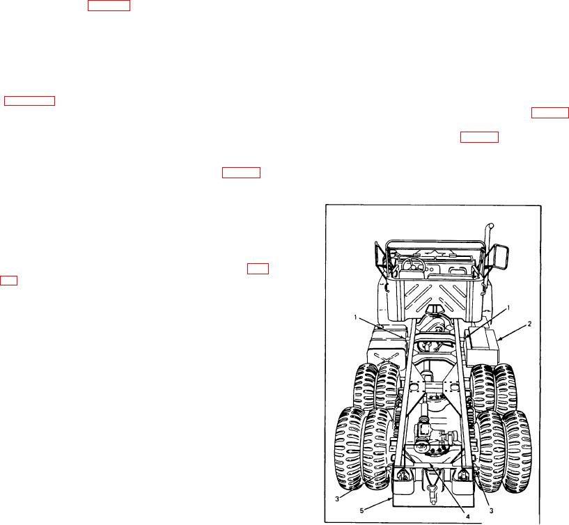
Figure 38
Chassis Components to be Removed
1. Left and Right Tie Down
4. Wiring Harness
2. Tool Box
5. Rear Cross Member
3. Glad Hands
36