
TM 5-3895-356-14&P
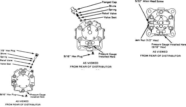
TYPE III HYDRAULIC MOTOR
TYPE II HYDRAULIC MOTOR
HYDRAULIC MOTOR RELIEF
PRESSURE ADJUSTMENT
If pump and motor case dram
rate and air leaks are not a problem,
proceed to adjust hydraulic motor
relief pressure as outlined below
First, determine which of the
three types of hydrostatic motor has
been installed on your distributor
Then adjust pressure as indicated for
the particular motor involved
TYPE I HYDRAULIC MOTOR
Figure 34
1. Loosen jam nut (1/2" hex)
and turn 5/32" Allen head screw m so
Figure 33
as to increase pressure A pressure
increase of 800 PSI per turn may be
1. Remove flanged cup casting
expected
located as shown on rear of hydraulic
2. Increase
pressure
to
motor This contains relief valve,
recommended level of 4000 to 4500
spring and shims
P S.I
2. Add required number of
3. Retighten jam nut while
shims so as to increase pressure to
holding screw.
recommended level of 4000 to 4500
Figure 32
4. Remove gauge and replace
P S.I Pressure may be increased at
9/16" hex plug
1. Of the two 7/8" plugs, located
the rate of 50
PSI
per one
on top of the motor, remove the one
thousandth (001") of shim.
CAUTION
nearest the universal coupling
3. Before replacing apply dab of
between motor and Etnyre asphalt
petroleum jelly or vaseline on
1. Throughout
the
entire
pump.
assembly to prevent RELIEF valve
operation, hands , parts, tools and
2. Exercise care m removal of
and spring from dropping out.
immediate area must be kept clean
this plug, spring, shims and relief
4. Re-check
pressure
and
Introduction of foreign material into
valve Should valve and spring fall
make additional adjustments If
the system may damage or hinder its
into discharge port, they may be
necessary
operation.
retrieved with a pencil magnet.
5. Remove gauge and replace
3. Add required number of
9/16" plug.
2. Do not operate the hydraulic
shims so as to increase pressure to
motor at maximum by-pass pressure
recommended level of 4000 to 4500
for extended periods of time since
P S I Pressure may be increased at
this will cause overheating of
the rate of 50 P I per one
hydraulic oil and result in system
thousandth ( 001") of shim.
damage
4. Before replacing plug, apply
a dab of petroleum jelly or vaseline
3. Recommended
relief
on end of tube to prevent valve,
pressure 4000 to 4500 P.S.I
spring and shims from dropping out
5. Re-check
pressure
and
4. For accessibility, removal of
make additional adjustments if
bar box or center platform is
necessary
recommended.
6. Remove gauge and replace
9/16" plug
26