TM 5-3895-356-14& P
HYDROSTATIC MOTOR PRESSURE ADJUSTMENT
1. Disconnect case return line
of 1000 R P M. If not, set
Equipment required for pressure
indicated above.
truck engine at fast Idle.
check
2. Attach flow meter as noted or
4. Engage P T.O
1. 5000 P.S.I. pressure gauge.
direct dram flow into a
5. Pull out rear override control
2. 2 Ft. length of high pressure
container of known volume
until
hydraulic
motor
hose to fit gauge fitting and adaptor
for a given period of time,
pressure
registers
the
3. Anchor
adaptor
No
Then from dividing volume
highest reading This is by-
4BC4UFS or 6 BC4UFS or
by time, a flow rate can be
pass pressure.
equivalent.*
determined. If this flow rate
4. Anchor "O"-ring No. 383-4
PRESSURE EVALUATION
is above maximum allowed,
or M-383-6 or equivalent.*
With pressure gauge installed and
pump is worn internally and
5. Etnyre shim kit No. 740064.
hydraulic motor locked as indicated
should be replaced before
6. Vaseline or petroleum jelly.
above determine if by-pass pressure
proceeding
is actually low. If pressure Is not low
INITIAL PRESSURE CHECK
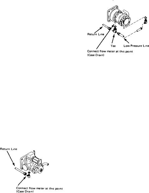
B. Motor case drain flow rate
consult "Trouble Shooting" section of
1. On bottom of hydraulic motor
this manual for other items which
check
remove right hand, 9/16" plug.
may cause hydraulic motor to turn
2. In this opening install a
slow or not at all If pressure is low
minimum
capacity 5000 P.S.I.
check the following two items before
gauge using appropriate Anchor
attempting
to
increase
relief
adaptor and "O"- ring with high
pressure.
pressure hose.
1. Air drawn into the hydraulic
3. Lock hydraulic motor by one
oil will cause it to appear
of the two following means and take
milky m color and result m
a pressure reading.
low system pressure To
A. MATERIAL IN DISTRIBUTOR
overcome this, check for air
TANK
leaks at four connections in
1. Set distributor controls on
the line from oil reservoir to
"Hand Spray" position See
Figure 31
filter to hydraulic pump.
section on "Hand Spraying"
Tighten fittings to eliminate
for additional information
1. Disconnect low pressure line
leaks
2. Transfer valve control (under
at motor tee If flow from this
2. Next check pump and motor case
left
operators
platform)
line Is directed into a clean
drain rate Maximum drain
remains in distribute position.
dry container the oil may be
rate is one-half (1/2) gallon
3. Accelerate to a minimum 100
saved and returned to the
per minute per 1000 P S I
G.P.M reading on pump
reservoir
Extreme
care
For example if the initial
Close
hand
should be taken to insure
pressure reading was 3000 P
spray
pressure
control
that while this line is
S I, the maximum allowable
"Butterfly Valve" slowly until
disconnected the hydraulic
flow rate would be 1 1/2 G.P
hydraulic
motor
stops
system is not accidentally
M
Highest reading on gauge is
pumped dry resulting m a
by-pass pressure setting on
damaged system
A. Pump case drain flow rate
hydraulic motor.
2. Disconnect return line and
check
remove tee from motor
B. EMPTY DISTRIBUTOR TANK
3. Connect flow meter as
1. On instrument stand in truck
indicated above or direct flow
cab pull pump control knob
from tee port (case dram)
to its uppermost position.
into a container of known
Adjust fine control tube up
volume for a given period of
until it is against bottom of
time Then from dividing
hydraulic control knob.
volume by time a flow rate
2. At the rear of distributor lock
can be determined. If this
universal coupling between
flow rate is above maximum
Etnyre pump and hydraulic
allowed motor is worn
*Select appropriate adaptor and
Figure 30
internally and should be
"O"-ring for the hydraulic motor
replaced before proceeding
motor with a pipe wrench of
sufficient length to lay
against left distributor frame.
3. If
truck
engine
has
tachometer, set to minimum
25

