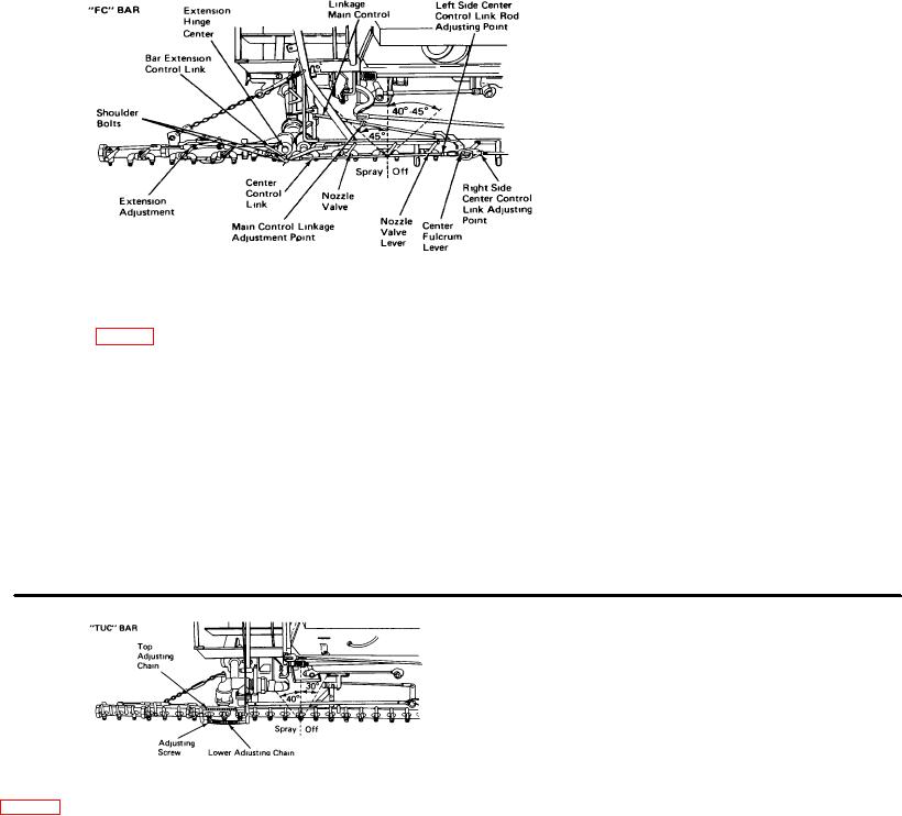
SPRAY BAR VALVE ADJUSTMENT
B. Align left side shoulder bolt
to center of extension lunge A rod
inserted through shoulder bolt hole to
extension hinge will aid in checking
alignment If necessary, heat and
bend bar extension control link to
obtain proper alignment.
Verify
proper alignment by raising bar with
rod or shoulder bolt in place-nozzle
valves should not move.
C. Check for proper nozzle
valve lever travel on center section
extension
and
any
additional
extensions The valve levers should
move 45 degrees to the left of
vertical and 40 degrees to 45
Figure 35
degrees to the right of vertical Adjust
if necessary
movement indicates worn linkage
Note Quadrant lever is
D. Connect left center control
that should be replaced
identified on Page 6.
linkage and adjust for proper left
3. Shoulder bolts that connect
1. Nozzle valve levers should
center section nozzle valve lever
bar extension control link to center
be 40 degrees to 45 degrees to right
travel
control link should center on
of vertical when quadrant control
E. Repeat steps B, C and D for the
extension hinge when valves are In
lever is to the left in "Circulate m Bar"
right side of bar
"Off" position
position and 45 degrees to left of
F.
Finally, adjust at main
If any discrepancy is found in
vertical when lever is in "Distribute"
control linkage, relationship of nozzle
the
preceeding,
correct
by
position
valve lever position to quadrant
completing the following spray bar
2.
Nozzle valve levers
control position, per item one
nozzle valve adjustment procedure
should start to move when quadrant
Do not fold extensions when
A. Disconnect main control
lever is moved 1" or less More
valves are turned on Do not attempt
linkage and both center control
to spray center of bar with extensions
linkages from center fulcrum lever.
folded without removing shoulder
bolts controlling extensions
the extension valve levers If
vertical and 40 degrees to left.
movement occurs or chains are not
tight, make the corresponding
adjustment having first disconnected
the chains on the lower left and
upper right
4. Throw quadrant lever to
spray position and extension valve
levers to 40 degrees left of vertical In
Figure 36
this position the lower left and upper
Note Quadrant lever Is identified on
right chains should be tight Since the
3.
Work
extension
lever arms operating the chains are
nozzle valves to check for binding,
1. Fold extensions back and
of different lengths, the lower left and
then throw valve levers 30 degrees to
adjust control linkage in
center
upper right will be loose when valves
right of vertical (off position) Turn
section so that valve levers are
are thrown to "Circulate In Bar"
quadrant lever to extreme left
vertical when quadrant lever Is 1" to
position, and the upper left and lower
position ("Circulate in Bar") Return
left of 45 degree position
right will be loose In the "Distribute"
extensions
to
the
forward
2. Throw quadrant lever to left
position When adjusted per above,
straightened position The adjustable
and right against stops and check
valves should work easily and there
connecting chains on the upper left
throw of nozzle valve levers Nozzle
should be no overload on the chain
and lower right should become tight
valve levers should turn through
pins.
but should not cause movement of
approximately 30 degrees to right of
27

