
Section II - DESCRIPTION
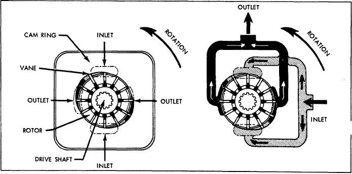
As the rotor is driven by the driveshaft, the vanes generate
A. GENERAL
fluid flow by carrying fluid around the elliptical ring contour
(see section m). Fluid enters the cartridge through the
Pumps in this series are used to develop hydraulic fluid
inlet port in the body and is discharged through the
flow for the operation of Mobile equipment. The positive
pressure plate to the outlet port in the cover.
displacement pumping cartridges are the rotary vane type
with shaft side loads hydraulically balanced. The flow rate
depends on the pump size and the speed at which it is
C. FLOW CONTROL AND RELIEF VALVE
driven.
V200 pumps are available with an integr Flow Control
All units are designed so that the direction of rotation,
and Relief Valve in the pump cover. This limits the fluid
pumping capacity and port positions can be readily
flow in the system to a maximum prescribed rate and
changed to suit particular applications.
prevents excessive pressure build-up. Fluid not required
in the system is recirculated to tank.
B. ASSEMBLY AND CONSTRUCTION
D. APPLICATION
The V200 series pump illustrated in cutaway in Figure
1 is representative of all single pumps in this series. The
Pump ratings in GPM as shown in the model coding are at
unit consists principally of a ported body and cover, a drive
1200 RPM.
For ratings at other speeds, methods of
installation and other application information, Vickers
shaft supported by two ball bearings, a pumping cartridge
Mobile Division Application engineering personnel should
and a pressure plate. The components of the cartridge are
be consulted.
an elliptical ring, a slotted rotor splined to the drive shaft
and twelve vanes fitted to the rotor slots.
Section III - PRINCIPLES OF OPERATION
Radial movement of the vanes and turning of the rotor
A. PUMPING CARTRIDGE
cause the chamber between the vanes to increase as the
vanes pass the inlet sections of the ring. This results in a
As mentioned in Section II;, fluid flow is developed in
low pressure condition which allows atmospheric pressure
the pumping cartridge. The action of the cartridge is
to force fluid into the chambers. (Fluid outside the inlet is
illustrated in Figure 2. The rotor is driven within the ring by
at atmospheric pressure or higher.)
the driveshaft, which is coupled to a power source.
As
the rotor turns, centrifugal force on the vanes causes them
to follow the elliptical inner surface of the ring.
Figure 2
4