
(4) Press out worn bushings "D." Examine bore of roller to be sure that the bore is clean and free from wear
marks.
(5) Press the new bushings into the rollers, being careful not to damage or distort the bushing while it is
being pressed into position.
NOTE: On earlier model pavers, seals were installed on each end of roller. When installing seals in these
assemblies, turn the lip of seals toward the outer edge of roller.
(6) Position roller in oscillating bracket and install shafts through bracket and rollers. Assemble both roller
shafts so grease fittings are on the same side of bracket. Assemble the shaft lock "C."
(7) Assemble the oscillating roller assembly into track frame making sure grease fittings are turned to the
outside of track.
(8) Lubricate with Texaco Marfax O until lubricant extrudes from assembly.
(9) After replacing all roller bushings the paver must be operated at slower travel speeds. Do not travel
paver in excess of 129 feet per minute for the first 10 miles. This will only pertain to traveling with the screed
raised. During "break in" period lubricate frequently. After "break in" lubricate every day as recommended in
lubrication chart.
Track Drive Chain Take-up (Figure 6).
To tighten the right or left drive chain "P" between the transfer Gear Case "Q" and drive sprocket "R" use the
following procedure.
(1) Loosen bolts "S" that hold transfer gear case "Q" in place.
(2) Loosen the jam nuts on adjusting screws "U" (four), then turn the screws downward to raise the transfer
case. When the chain tension is correct and the case is parallel to the frame, slip shims "T" under each side of
the case to retain the new position. The chain should have M" deflection on the slack side.
(3) Unscrew the four adjusting screws "U" so that they do not touch the frame and tighten their jam nuts to
keep them in place.
(4) Tighten bolts "S" to hold the transfer case solidly in place. Re-check chain tension to be sure it did not
change.
Crawler Track Drive Detail - R.H.
Figure 6
REPLACING TRACK DRIVE SPROCKETS
Track drive sprockets are made up of a hub assembly and two bolted-on tooth sections. When the sprocket
teeth are worn, these removable sections can be replaced in order to restore the sprocket teeth to new
condition. When attaching the new parts apply Locktite Sealant (Grade B) to the capscrew threads to help
prevent loosening. Sprocket tooth sections can be replaced without disconnecting the track.
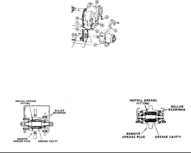
TRACK SPROCKET AND IDLER BREARING LUBRICATON
IMPORTANT! Once each seasons remove both grease plugs from the hubs of the two track sprockets and
the two track idlers. (see Figures 7 and 8). Install a grease fitting in the upper hole. Pump in fresh grease until
it is extruded steadily from the bottom hole. Replace hole plugs.
Cross-section thru Track Sprocket
Cross-section thru Track Idler
Figure 7
Figure 8
Page 101