
TM 5-3895-385-23-2
0417
Conveyor Drag Chain Tension Adjustment -- Continued.
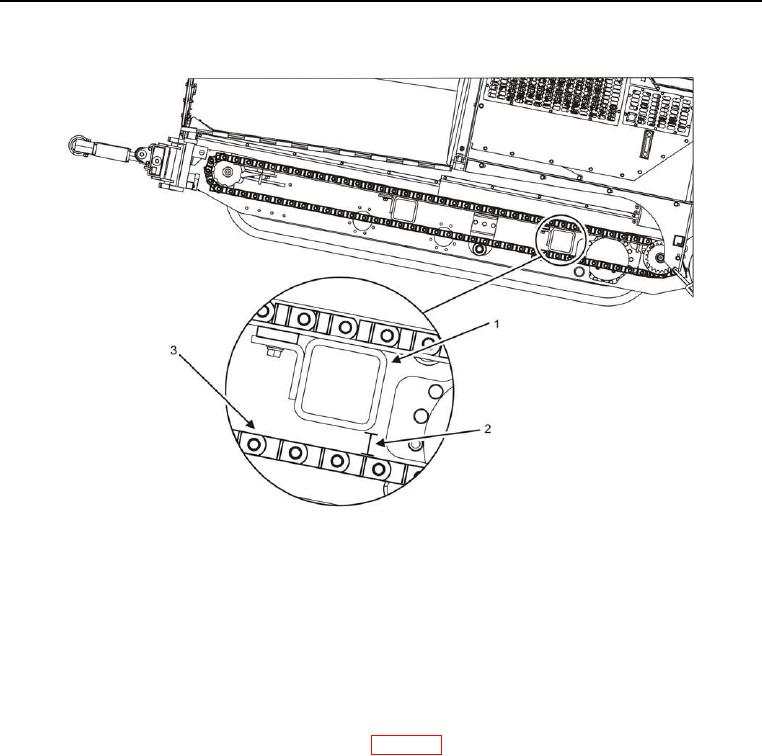
Figure 7. Conveyor Drag Chain Slack.
3. Turn two chain tensioner bolts (Figure 6, Item 3) equally on each conveyor drag chain until the gap between
the conveyor drag chain (Figure 7, Item 3) and rear frame tube (Figure 7, Item 1) is approximately one-half of
an inch (13 millimeters (mm)) (Figure 7, Item 2).
4. Tighten jam nut (Figure 6, Item 2).
END OF TASK
FOLLOW-ON TASK
1. Lower BMPM to ground, and remove lifting device (WP 0435).
2. Verify proper operation.
END OF TASK
END OF WORK PACKAGE
0417-11/12 blank