
TM 5-3895-385-23-2
0388
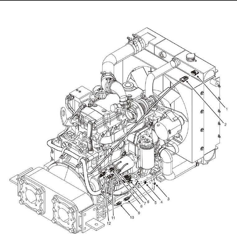
Engine Interface Wiring Harness Installation -- Continued.
Figure 3. Engine Interface Wiring Harness Left Side.
6. Connect yellow wire (Figure 3, Item 5) and install new lock washer (Figure 3, Item 4) and nut (Figure 3, Item
3) to starter solenoid (Figure 3, Item 6).
7. Connect W16 J6 (Figure 3, Item 11) to C17 J1 (Figure 3, Item 7).
8. Connect W16 J5 (Figure 3, Item 2) to coolant temperature sensor (Figure 3, Item 1).
9. Connect W16 J4 (Figure 3, Item 10) to W17 J1 (Figure 3, Item 9).
10. Connect W16 J1 (Figure 3, Item 12) to W1 J7 (Figure 3, Item 8).
END OF TASK