
TM 5-3895-385-23-2
0385
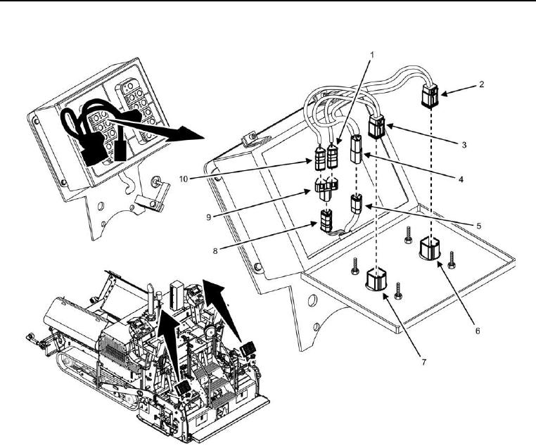
Right Side Screed Control Box Wiring Harness Removal -- Continued.
Figure 2. Right Side Screed Control Box Wiring Harness.
2. Disconnect W2 J3 (Figure 2, Item 1) from Y11 (Figure 2, Item 9) P3.
3. Disconnect W2 J4 (Figure 2, Item 10) from Y11 (Figure 2, Item 9) P2.
4. Disconnect Y11 (Figure 2, Item 9) P1 from W6 J4 (Figure 2, Item 8).
5. Disconnect W2 J5 (Figure 2, Item 4) from W6 J5 (Figure 2, Item 5).
6. Disconnect W2 J2 (Figure 2, Item 3) from screed auger/conveyor keypad (Figure 2, Item 7).
7. Disconnect W2 J1 (Figure 2, Item 2) from screed horn keypad (Figure 2, Item 6).
END OF TASK