
TM 5-3895-385-23-2
0306
LIQUID SIGHT INDICATOR REMOVAL AND INSTALLATION
Liquid Sight Indicator Removal
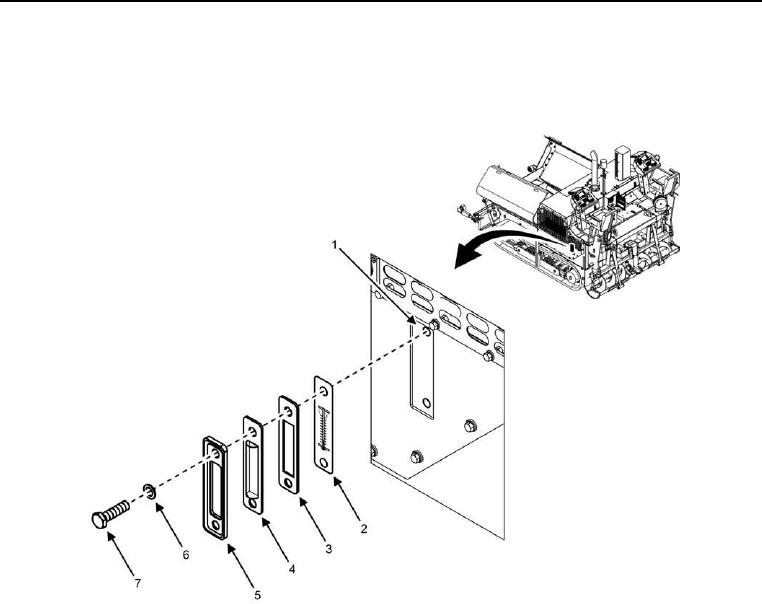
Figure 1. Liquid Sight Indicator.
Remove two bolts (Figure 1, Item 7), flat washers (Figure 1, Item 6), outer cover (Figure 1, Item 5), inner cover
(Figure 1, Item 4), gasket (Figure 1, Item 3), and thermometer (Figure 1, Item 2) from hydraulic tank (Figure 1,
Item 1).
END OF TASK
Liquid Sight Indicator Installation
Install two bolts (Figure 1, Item 7), flat washers (Figure 1, Item 6), outer cover (Figure 1, Item 5), inner cover
(Figure 1, Item 4), gasket (Figure 1, Item 3), and thermometer (Figure 1, Item 2) onto hydraulic tank (Figure 1,
Item 1).
END OF TASK