
TM 5-3895-385-23-2
0268
KEYLESS ENGINE SWITCH REMOVAL AND INSTALLATION
Keyless Engine Switch Removal
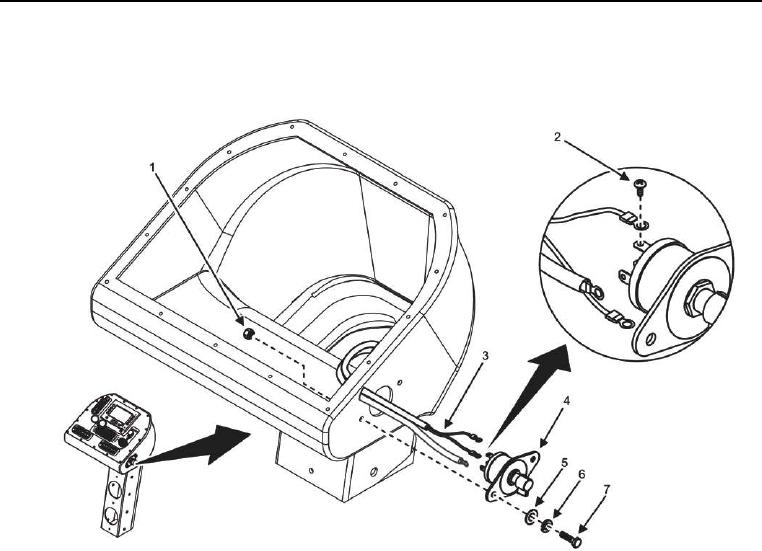
Figure 1. Keyless Engine Switch.
CAUTION
Tag and label electrical wires prior to removal. Electrical wires must be installed correctly for
proper operation. Failure to comply may cause damage to equipment.
1. Remove three screws (Figure 1, Item 2) and cables (Figure 1, Item 3) from keyless engine switch (Figure 1,
Item 4).
2. Remove two bolts (Figure 1, Item 7), lock washers (Figure 1, Item 6), flat washers (Figure 1, Item 5), nuts
(Figure 1, Item 1), and keyless engine switch (Figure 1, Item 4) from pedestal assembly. Discard lock
washers.
END OF TASK
Keyless Engine Switch Installation
1. Install two bolts (Figure 1, Item 7), new lock washers (Figure 1, Item 6), flat washers (Figure 1, Item 5), nuts
(Figure 1, Item 1), and keyless engine switch (Figure 1, Item 4) into pedestal assembly.
2. Install three screws (Figure 1, Item 2) and cables (Figure 1, Item 3) onto keyless engine switch (Figure 1, Item
4).
END OF TASK