
TM 5-3895-385-23-2
0264
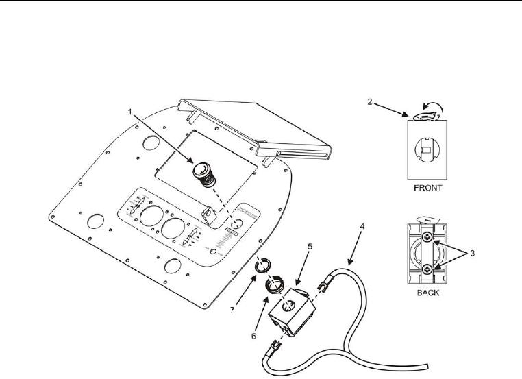
EMERGENCY STOP SWITCH REMOVAL AND INSTALLATION
EMERGENCY STOP Switch Removal
Figure 1. EMERGENCY STOP Switch.
1. Move locking tab (Figure 1, Item 2) to the right, and remove EMERGENCY STOP switch control box (Figure
1, Item 5) from EMERGENCY STOP switch (Figure 1, Item 1).
2. Remove nut (Figure 1, Item 6) and spacer (Figure 1, Item 7) from EMERGENCY STOP switch (Figure 1, Item
1).
3. Remove EMERGENCY STOP switch (Figure 1, Item 1) from pedestal assembly.
CAUTION
Tag and label electrical cables prior to removal. Electrical cables must be installed correctly for
proper operation. Failure to comply may cause damage to equipment.
4. Loosen screws (Figure 1, Item 3), and disconnect cables (Figure 1, Item 4) from EMERGENCY STOP switch
control box (Figure 1, Item 5).
END OF TASK