
TM 5-3895-385-23-2
0257
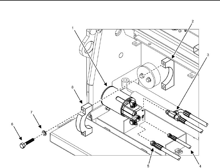
Left Screed Vibrator Assembly Installation.
Figure 9. Left Screed Vibrator Assembly -- Installation.
1. Install two bolts (Figure 9, Item 6), new lock washers (Figure 9, Item 7), vibrator assembly (Figure 9, Item 1),
and clamp (Figure 9, Item 8) onto mounting point (Figure 9, Item 2).
2. Remove caps from hydraulic hoses (Figure 6, Items 3, 4, and 5).
3. Install hydraulic hoses (Figure 6, Items 3, 4, and 5) at hydraulic fittings on vibrator assembly (Figure 6, Item
1).
END OF TASK