
TM 5-3895-385-23-2
0257
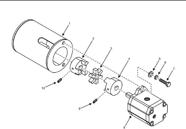
Left Screed Vibrator Assembly Disassembly
Figure 7. Left Screed Vibrator Hydraulic Motor -- Removal/Installation.
1. Remove two bolts (Figure 7, Item 7), lock washers (Figure 7, Item 6), flat washers (Figure 7, Item 5), and
vibrator hydraulic motor (Figure 7, Item 8) from vibrator assembly (Figure 7, Item 1). Discard lock washers.
2. Remove two couplers (Figure 7, Items 2 and 4), set screws (Figure 7, Items 9 and 10), and flexible coupling
insert (Figure 7, Item 3) from vibrator hydraulic motor (Figure 7, Item 8).
END OF TASK