
TM 5-3895-385-23-2
0257
Left Screed Vibrator Assembly Removal -- Continued.
WARNING
Support components when removing/installing the attaching hardware or when component may
fall. Failure to comply may cause injury or death to personnel and damage to equipment.
2. Remove two bolts (Figure 5, Item 6), lock washers (Figure 5, Item 7), vibrator assembly (Figure 5, Item 1),
and clamp (Figure 5, Item 8) from mounting point (Figure 5, Item 2). Discard lock washers.
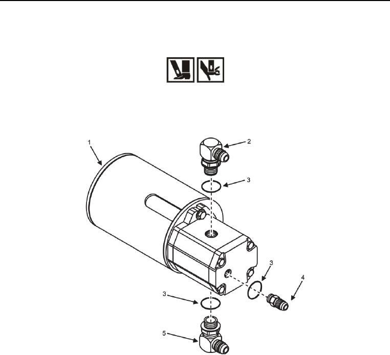
Figure 6. Right Screed Vibrator Assembly Connectors -- Removal.
3. Remove three hydraulic fittings (Figure 6, Items 2, 4, and 5) along with O-rings (Figure 6, Item 3) from vibrator
assembly (Figure 6, Item 1). Discard O-rings.
END OF TASK