
TM 5-3895-385-23-2
0257
Left Screed Vibrator Assembly Assembly
1. Install two couplers (Figure 7, Items 2 and 4), set screws (Figure 7, Items 9 and 10), and flexible coupling
insert (Figure 7, Item 3) onto vibrator hydraulic motor (Figure 7, Item 8).
2. Install two bolts (Figure 7, Item 7), new lock washers (Figure 7, Item 6), flat washers (Figure 7, Item 5), and
vibrator hydraulic motor (Figure 7, Item 8) onto vibrator assembly (Figure 7, Item 1).
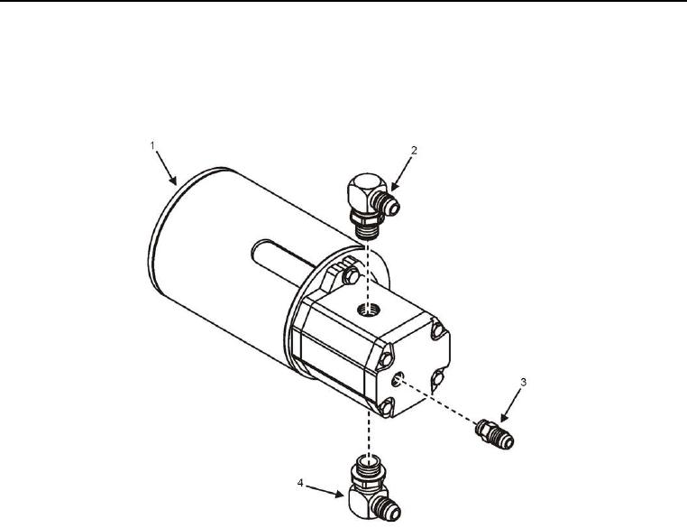
Figure 8. Right Screed Vibrator Assembly Connectors -- Installation.
3. Install three hydraulic fittings (Figure 8, Items 2, 3, and 4) along with two new O-rings (Figure 6, Item 3) onto
vibrator assembly (Figure 8, Item 1).
END OF TASK