
TM 5-3895-385-23-2
0250
Screed Main Wear Plate Installation -- Continued.
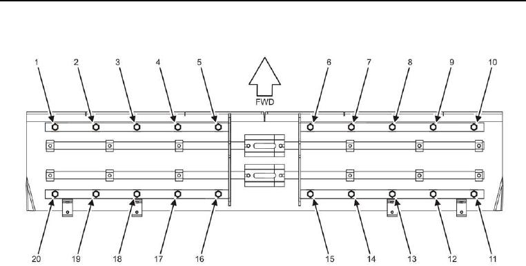
Figure 6. Screed Main Wear Plate Bolts--Installation.
6. Install five bolts (Figure 6, Items 1, 2, 3, 4, and 5), new lock washers (Figure 7, Item 3), and bevel washers
(Figure 7, Item 4) into screed (Figure 7, Item 1) and screed wear plate (Figure 7, Item 5) finger-tight.
NOTE
It may be necessary to move the screed wear plate and activate the screed crown and valley
keys (TM 5-3895-385-10) to align the screed mounting holes with the screed wear plate mounting
holes.
7. Install five bolts (Figure 6, Items 6, 7, 8, 9, and 10), new lock washers (Figure 7, Item 3), and bevel washers
(Figure 7, Item 4) into screed (Figure 7, Item 1) and screed wear plate (Figure 7, Item 5) finger-tight.
8. Install 10 bolts (Figure 6, Items 11, 12, 13, 14, 15, 16, 17, 18, 19, and 20), new lock washers (Figure 7, Item
3), and bevel washers (Figure 7, Item 4) into screed (Figure 7, Item 1) and screed wear plate (Figure 7, Item
5) finger-tight.
9. Tighten two bolts (Figure 6, Items 5 and 16).
10. Tighten two bolts (Figure 6, Items 6 and 15).
11. Tighten two bolts (Figure 6, Items 4 and 17).
12. Tighten two bolts (Figure 6, Items 7 and 14).
13. Tighten two bolts (Figure 6, Items 3 and 18).
14. Tighten two bolts (Figure 6, Items 8 and 13).
15. Tighten two bolts (Figure 6, Items 2 and 19).
16. Tighten two bolts (Figure 6, Items 9 and 12).
17. Tighten two bolts (Figure 6, Items 1 and 20).
18. Tighten two bolts (Figure 6, Items 10 and 11).