
TM 5-3895-385-23-2
0243
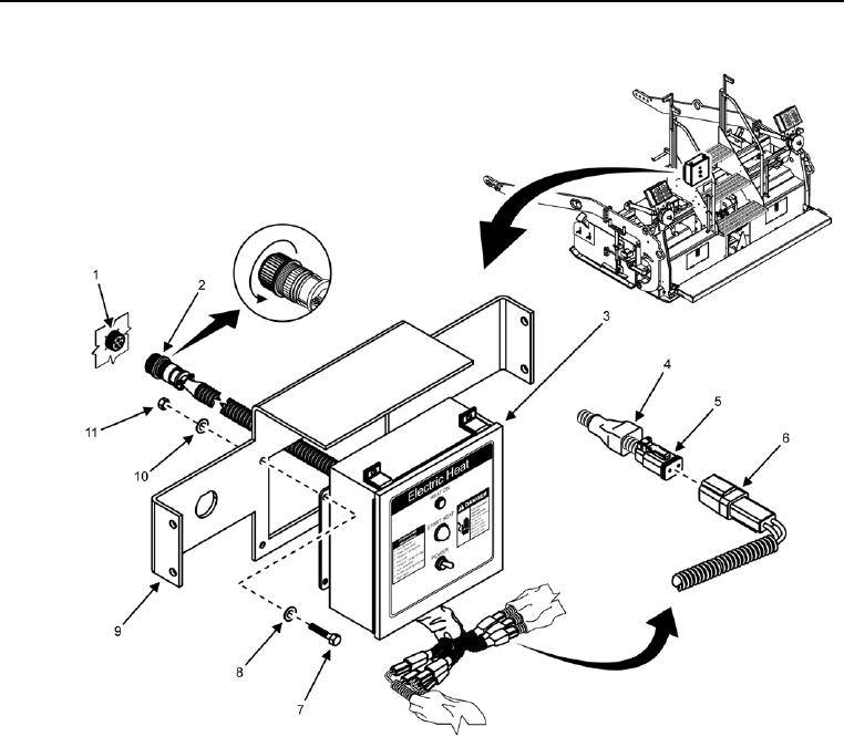
Screed Electric Heat Box Installation
Figure 15. Screed Electric Heat Box -- Installation.
1. Install four bolts (Figure 15, Item 7), eight flat washers (Figure 15, Items 8 and 10), and four new locking nuts
(Figure 15, Item 11) onto screed electric heat box (Figure 15, Item 3) and bracket (Figure 15, Item 9).
2. Connect W23 J1 (Figure 15, Item 2) to W22 J3 (Figure 15, Item 1), and secure cable safely away from any
pinch points with wire ties while allowing for full range of motion of the screed and all other moving parts.
3. Connect six screed heat box connectors (Figure 15, Item 5) to six screed heater element connectors (Figure
15, Item 6).
4. Slide dust boot (Figure 15, Item 4) over screed heat box connector (Figure 15, Item 5).
END OF TASK