
TM 5-3895-385-23-2
0230
Rear Screed Arm Removal
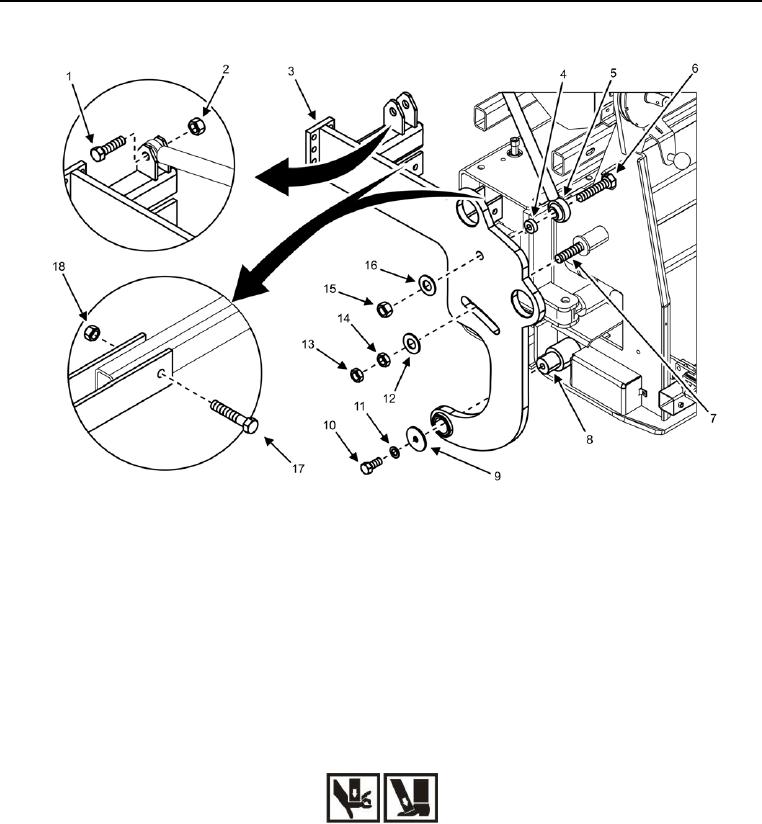
Figure 7. Rear Screed Arm -- Removal/Installation.
1. Remove front screed arm (perform steps 1 8 of Front Screed Arm Removal task) from rear screed arm
(Figure 7, Item 3).
2. Remove bolt (Figure 7, Item 6), spacer (Figure 7, Item 4), flat washer (Figure 7, Item 16), nut (Figure 7, Item
15), and screed raise hydraulic cylinder (Figure 7, Item 5) from rear screed arm (Figure 7, Item 3).
3. Remove bolt (Figure 7, Item 1) and locking nut (Figure 7, Item 2) from rear screed arm (Figure 7, Item 3).
Discard locking nut.
4. Remove bolt (Figure 7, Item 10), lock washer (Figure 7, Item 11), and flat washer (Figure 7, Item 9) from
lower hinge point (Figure 7, Item 8). Discard lock washer.
WARNING
Support components when removing/installing the attaching hardware or when component may
fall. Failure to comply may cause injury or death to personnel and damage to equipment.
5. Remove two bolts (Figure 7, Item 17) and locking nuts (Figure 7, Item 18) from top bar and screed arm
(Figure 7, Item 3). Discard locking nuts.
6. Remove jam nut (Figure 7, Item 13), jam nut (Figure 7, Item 14), and flat washer (Figure 7, Item 12) from
upper hinge point (Figure 7, Item 7).