TM 5-3895-373-34
A.
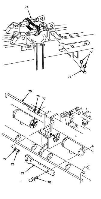
REMOVE - Continued.
9.
DISCONNECT AND LAY ASIDE CROWN
ADJUSTMENT ASSEMBLY.
WARNING
Use care when removing retaining
rings. Retaining rings are under
spring
tension
and
can
act
as
projectiles when released and could
cause severe eye injury.
NOTE
Remove only the side of the crown
adjustment
assembly
from
main
screed frame being replaced.
Right hand main screed frame is
shown in this procedure.
a.
Remove retaining rings (72) using snap ring
pliers.
b.
Remove both mounting pins (73) from side of
main screed frame being replaced.
c.
Lift loosened side of crown adjustment assembly
(74) and lay to one side, against other main
screed frame.
d.
Use a marker and mark position of pointer (75)
for reassembly.
e.
Remove hex nuts (76), lockwashers (77), and
pointer (75) from right hand main screed frame.
Discard lockwashers.
f.
Remove
thumbscrews
(78)
and
crown
adjustment wrench (79), if required, from right
hand main screed frame.
g.
Measure distance between main screed frames
with a machinist’s steel rule. Record this
measurement. It will be used to align main
screed frames in step D.1.e and D.5.h.
h.
Remove C-clamp and spacer wedges from
between left hand and right hand main screed
frames installed in paragraph 2.71 step B.3.
GO TO NEXT PAGE
2-937