TM 5-3895-373-34
D.
REPLACE - Continued.
6.
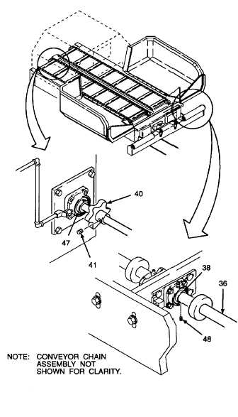
ALIGN CONVEYOR CHAIN ASSEMBLY.
a.
Visually check conveyor chain assembly in
tunnel opening. Chain assembly should be
centered in tunnel opening with sprocket
wheels (40) equal distance from bearing
units (47). If not, remove set screws (41)
on
both
sprocket
wheels
and
move
sprocket wheels to center conveyor chain
assembly in tunnel opening. Keep the
distance between sprocket wheels the
same as the chain assembly width.
Thread locking compound can cause eye
damage. Wear safety goggles/glasses when
using.
Avoid
contact
with
eyes.
If
compound contacts eyes, flush eyes with
water and get immediate medical attention.
b.
Apply thread locking compound to threads
of set screws (41).
c.
Install set screw (41). Tighten set screws
using socket wrench adapter and hex head
driver socket (Item 86, Appendix D) to 90
Ib-ft (122 N•m).
NOTE
After
the
conveyor
chain
assembly
is
installed on conveyor roller wheels and
sprocket wheels, it will be necessary to run
the conveyor to center the idler end of the
chain assembly and conveyor roller shaft.
d.
Loosen set screws (48) on bearing units
(38) at both ends of conveyor roller shaft
(36).
Use extreme caution when conveyor and
auger are operating. Stay clear of all moving
parts. Failure to do so may result in tools,
clothing, hands, or feet getting caught and
causing serious injury or death to personnel.
e.
Start engine and run conveyor in forward
direction
using
manual
operation
procedures
per
TM
5-3895-373-10.
Visually check alignment of conveyor chain
assembly and roller shaft (36). Chain
assembly should be running either in
center, or slightly off center without hitting
sides of machine frame. Stop conveyor.
Shut off engine and remove key from
ignition switch per TM 5-3895-373-10.
GO TO NEXT PAGE
2-847