TM 5-3895-373-34
A.
DISASSEMBLE.
NOTE
Use bench vise, as required, to support
auger/conveyor control valve during
disassembly.
1.
REMOVE ELBOW, SWIVEL ELBOW, STRAIGHT
ADAPTERS,
THREADED
END
RODS,
AND
ANGLE BRACKETS FROM AUGER/CONVEYOR
CONTROL VALVE.
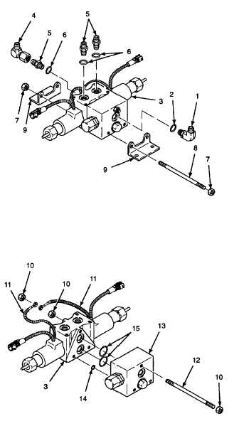
a.
Loosen elbow locking nut and remove elbow (1)
and preformed packing (2) from auger/conveyor
control valve (3). Discard preformed packing.
b.
Remove swivel elbow (4), straight adapters (5)
and
preformed
packings
(6)
from
auger/conveyor control valve (3). Discard
preformed packings.
c.
Remove self-locking hex nuts (7) from threaded
end rods (8). Discard self-locking hex nuts.
d.
Remove threaded end rods (8) and angle
brackets (9) from auger/conveyor control valve
(3).
2.
REMOVE
RELIEF
VALVE
ASSEMBLY
AND
THREADED
END
RODS
FROM
AUGER/
CONVEYOR CONTROL VALVE.
a.
Remove self-locking hex nuts (10) and ground
wires (11) from threaded end rod (12). Discard
self-locking hex nuts.
b.
Remove
threaded
end
rod
(12)
from
auger/conveyor control valve (3).
c.
Separate relief valve assembly (13) from auger/
conveyor control valve (3).
d.
Remove special shims (14) from relief valve
assembly. Discard special shims.
Use caution when removing seals and
preformed packings.
Scratched
or
dented seal grooves can cause bypass
leakage. Do not use excessive force
when removing seals and preformed
packings. Use an o-ring tool to remove
seals and preformed packings.
e.
Use o-ring tool to remove preformed packings
(15) from relief valve assembly (13). Discard
preformed packings.
GO TO NEXT PAGE
2-621