TM 5-3895-373-34
2.33
REPLACE/REPAIR SPEED REDUCTION GEARBOX - Continued.
B.
DISASSEMBLE - Continued.
Use care when removing snap and
retaining rings. Snap and retaining
rings are under spring tension and
can act as projectiles when released
and could cause severe eye injury.
p.
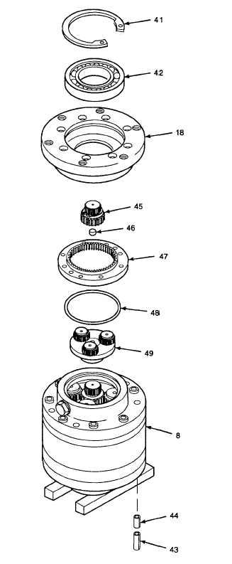
Use snap ring pliers to remove retaining
ring (41) from mechanical drive housing
(18). Discard retaining ring.
q.
Use bearing puller from universal puller kit
to remove bearing (42) from mechanical
drive housing (18). Discard annular ball
bearing.
2.
REMOVE
SPEED
REDUCTION
GEARBOX
COMPONENTS.
a.
Stand speed reduction gearbox (8) on
wooden support blocks, as shown. Locate
spring pin holes off edge of work surface to
allow clearance for removal of spring pins
(43 and 44).
b.
Use 3/8 in. diameter metal bars and drive
pin punch to drive spring pins (43 and 44)
out
of
speed
reduction
gearbox
(8).
Discard spring pins.
c.
Remove spur gear (45), thrust washer
bearing (46), internal gear (47), o-ring (48),
and speed reducer gearset (49). Discard
thrust washer bearing and o-ring.
GO TO NEXT PAGE
2-476


