TM 5-3895-373-34
2.19
REPLACE/REPAIR FUEL INJECTION PUMP - Continued.
E.
ASSEMBLE - Continued.
d.
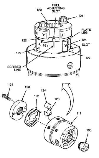
Position pump plate assembly (127) on
rotor head assembly. Line up slots on plate
assembly with cutouts on inner rotor head
assembly (125). Refer to illustration.
e.
Insert inner rotor head assembly (125) into
outer rotor head assembly (111).
f.
Install roller shoes (123) and rollers (124)
into inner rotor head assembly (125).
g.
Install
pump
plate
assembly
(122),
chamfered edges facing down, and engage
plate legs in slots of pump plate assembly
(127).
h.
Turn pump plate assemblies (127 and 122),
so fuel adjusting slot in plate assembly
(122) lines up with scribe line on inner rotor
head assembly (125).
i.
Install governor hub (120), with machined
side facing down, and slot between letters
"A" and "H" aligned with pump plate
assembly (122).
j.
Install drive screws (121) into governor hub
(120) hand tight.
k.
Install pump -impeller (105) into outer rotor
head assembly (111) hand tight.
GO TO NEXT PAGE
2-272


