TM 5-3895-373-20
C.
INSTALL - Continued.
2.
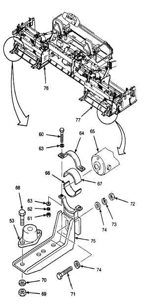
ASSEMBLE AND INSTALL OUTER STEP
SUPPORTS.
a.
Place outer step supports (75) on extension
screeds (76 and 77).
Thread locking compound can cause
eye
damage.
Wear
safety
goggles/glasses when using. Avoid
contact with eyes. If compound
contacts eyes, flush eyes with water
and get immediate medical attention.
b.
Place flat washers (74) onto hex head cap
screws (71) and apply thread locking compound
(Item 12, Appendix C) to threads of hex head
cap screws.
c.
Secure outer step supports (75) with hex head
cap screws (71), flat washers (74), lockwashers
(73), and hex nuts (72). Tighten hex nuts to 37
lb-ft (50 N•m).
d.
Position vibration mounts (53) on outer step
supports (75).
e.
Apply thread locking compound (Item 13,
Appendix C) to threads of bolts (68).
f.
Secure vibration mounts (53) to outer step
supports (75) with bolts (68), flat washers (70),
and hex nuts (69). Tighten hex nuts to 19 lb-ft
(26 N•m).
g.
Set lower cushion (66) onto motor cradles of
outer step supports (75).
h.
Place blower motors (65) onto lower cushion
(66).
i.
Place upper cushion (67) and blower motor
clamps (64) over blower motors (65).
j.
Place flat washers (63) onto hex head cap
screws (60) and apply thread locking compound
(Item 13, Appendix C) to hex head cap screws.
k.
Secure blower motor clamps (64) with hex head
cap screws (60), flat washers (63), lockwashers
(62), and hex nuts (61). Tighten hex nuts
evenly.
GO TO NEXT PAGE
11-25