TM 5-3895-373-20
2.24.3. SCREED REMOVAL AND INSTALLATION.
This task covers:
a. Remove
b. Install
INITIAL SETUP
Tools:
General mechanic’s automotive tool kit
(Item 54, Appendix E)
Crowbars, 2 ea (Item 11, Appendix E)
Drip pan (Item 28, Appendix E)
High pressure caps, 2 ea (Item 8, Appendix E)
Screwdriver bit set (Item 37, Appendix E)
Torque wrench (Item 68, Appendix E)
Materials/Parts:
Cleaning cloth (Item 7, Appendix C)
Electrical insulating compound (Item 11, Appendix C)
Hydraulic fitting sealant (Item 21, Appendix C)
Lint-free cloth (Item 8, Appendix C)
Machinery wiping towel (Item 30, Appendix C)
Tags (Item 27, Appendix C)
Thread locking compound (Item 12, Appendix C)
Thread locking compound solvent (Item 25, Appendix C)
Tie wraps (Item 29, Appendix C)
Protective caps (Item 5, Appendix C)
Personnel Required:
Three 62B construction equipment repairers. Additional
persons needed to hold drip pan, to help remove and
install screed lift clevis pins, and to act as spotters for
driving tractor away from and toward screed.
References:
TM 5-3895-373-10
Equipment Condition:
Screed lowered onto level concrete or asphalt surface
per
TM 5-3895-373-10.
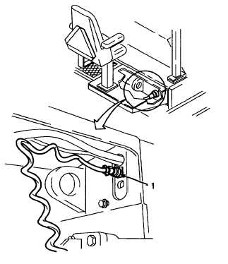
NOTE
Disconnection procedure for left hand and right hand
feed limit switch harness connectors is the same. Right
hand feed limit switch harness connector is shown in this
procedure.
A.
REMOVE.
1. UNPLUG SCREED HARNESS CONNECTORS.
a.
Unscrew and unplug feed limit switch harness
connectors (1) from left and right hand sides of
tractor bulkhead.
GO TO NEXT PAGE
2-455