TM 5-3895-373-20
15.11.
REPLACE SCREED EXTENSION CYLINDER.
This task covers:
a. Remove
b. Install
INITIAL SETUP
Tools:
References:
General mechanic’s automotive tool kit
TM 5-3895-373-10
(Item 54, Appendix E)
TM 5-3895-373-24P
Torque wrench (Item 68, Appendix E)
Equipment Condition:
Materials/Parts:
Extension screeds fully extended (if possible)
Cleaning cloth (Item 7, Appendix C)
per TM 5-3895-373-10.
Hydraulic fitting sealant (Item 21, Appendix C)
Hydraulic oil (Item 18, Appendix C)
Machinery wiping towels (Item 30, Appendix C)
Protective caps (Item 5, Appendix C)
Thread locking compound (Item 12, Appendix C)
Thread locking compound solvent (Item 25, Appendix C)
Screed extension cylinder
Lockwashers
Preformed packings
Self-locking machine screws
NOTE
This procedure applies to both the left and
right screed extension cylinders. In this
procedure the right screed extension cylinder
is shown.
A.
REMOVE.
1.
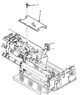
REMOVE SCREED COVER PLATE.
a.
Remove self-locking machine screws (1) from
screed cover plate (2). Discard self-locking
machine screws.
b.
Remove screed cover plate (2) from the paving
machine.
GO TO NEXT PAGE
15-77