TM 5-3895-373-20
NOTE
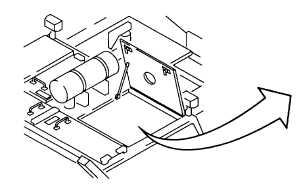
There is a left hand and a right hand flow
gate on the paving machine. This
procedure refers to replacement of right
hand flow gate components. Procedure is
identical
for
left
hand
flow
gate
components. Right hand flow gate
components are shown in this procedure.
A.
REMOVE.
1.
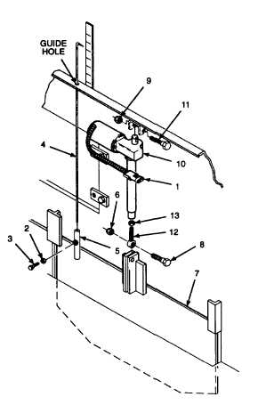
REMOVE LINEAR ACTUATOR.
a.
Unplug electrical connector (1) from the engine
harness.
NOTE
Indicator rod, indicator plate, or flow
gate, should be removed only as needed to
replace damaged components.
b.
Remove hex nut (2) and hex head cap screw (3).
Slide indicator rod (4) from clamping tube (5)
and guide hole.
c.
Remove and discard self-locking hex nut (6).
Support flow gate (7) and remove hex head cap
screw (8). Lower flow gate to bottom of slide.
d.
Remove and discard self-locking hex nut (9).
Support linear actuator (10) and remove hex
head cap screw (11). Remove linear actuator.
e.
Hold rod end (12) and loosen jam nut (13).
Unscrew rod end from linear actuator. Remove
jam nut.
GO TO NEXT PAGE
15-73