TM 5-3895-373-20
15.10.
REPLACE FLOW GATE COMPONENTS - Continued.
B.
INSTALL - Continued.
2.
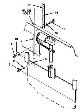
INSTALL INDICATOR PLATE AND ROD.
WARNING
Thread locking compound solvent can
cause
eye
damage.
Wear
safety
goggles/glasses
when
using.
Avoid
contact with eyes. If solvent contacts
eyes, flush eyes with water and get
immediate medical attention.
a.
Clean threads of hex head cap screws (15) with
thread locking compound solvent.
b.
Dry hex head cap screws with a cleaning cloth.
c.
Install lockwashers (16) on hex head cap screws
(15).
WARNING
Thread locking compound can cause eye
damage. Wear safety goggles/glasses
when using. Avoid contact with eyes. If
compound contacts eyes, flush eyes with
water
and
get
immediate
medical
attention.
d.
Apply thread locking compound to threads of
hex head cap screws (15).
e.
Install indicator plate (14), and hex head cap
screws (15). Make sure decal (21) is facing to
the rear of the paving machine. Tighten hex
head cap screws to 9 lb-ft (12 N.m).
f.
Slide indicator rod (4) through guide hole in top
of frame. Install straight end of indicator rod in
clamping tube (5).
g.
Turn indicator rod until pointer is parallel with
face of indicator plate (14).
h.
Clean threads of hex head cap screw (3) with
thread locking compound solvent.
i.
Dry hex head cap screw with a cleaning cloth.
j.
Install hex nut (2) onto hex head cap screw (3).
Screw hex nut on all the way up to head of hex
head cap screw.
k.
Apply thread locking compound to threads of
hex head cap screw (3).
l.
Adjust height of indicator rod to align pointer
with "CLOSED" mark on decal (21).
m.
Install and tighten hex head cap screw (3) into
clamping tube (5) against indicator rod (4).
Tighten hex nut (2) against clamping tube.
n.
Install bottom engine access cover brackets (18)
and hex head cap screws (17) and tighten cap
screws.
NOTE
FOLLOW-ON-TASKS:
Install engine access cover per paragraph 2.22.
Close front top right access door per TM 5-3895-373-10.
Close front top left access door per TM 5-3895-373-10.
END OF TASK
15-76