TM 53895-371-24 & P
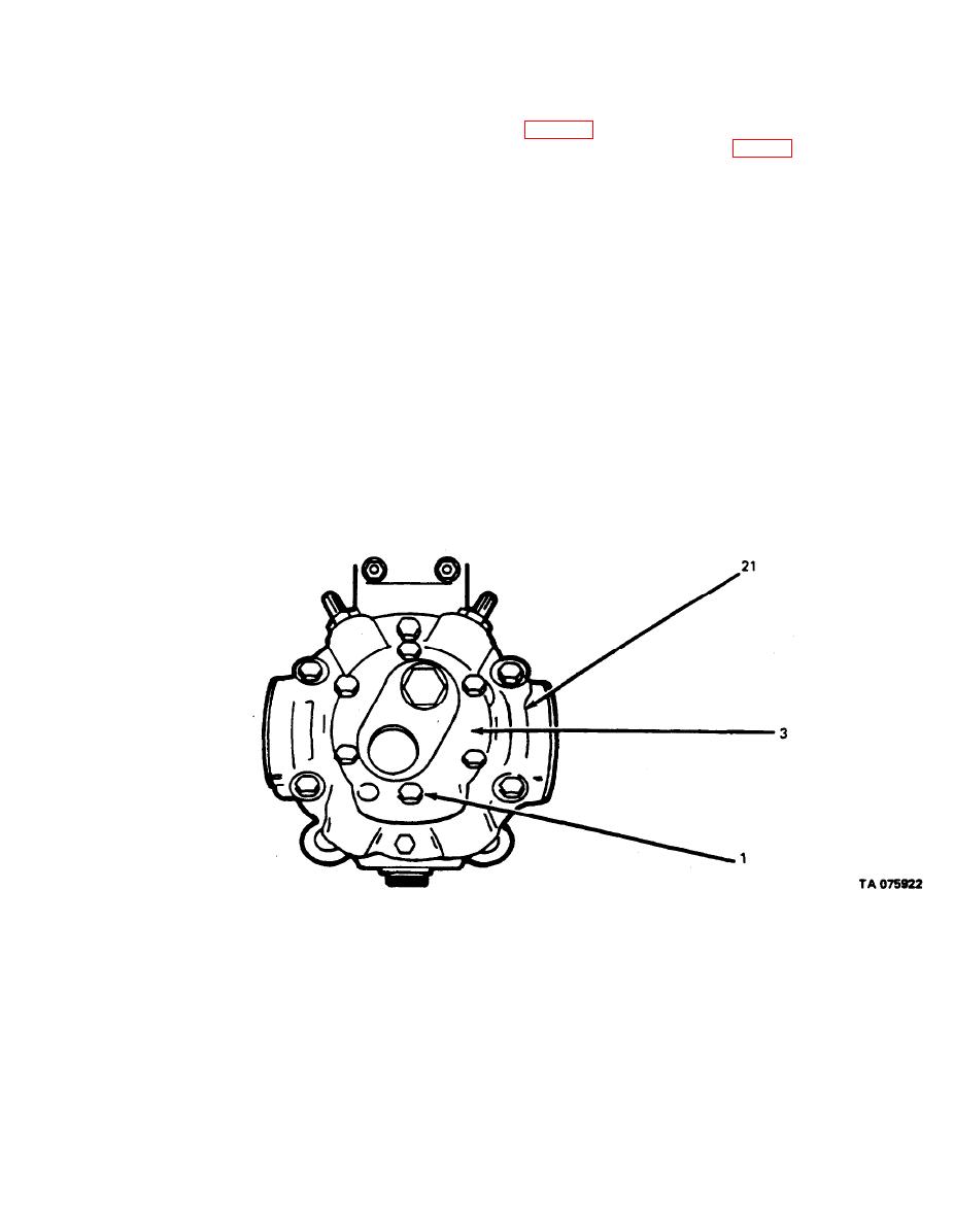
(33) Position pump cover (3) over plate (4) so that the spacer assembly dowel pin (6) alines
with roll pin hole in the pump cover (3). (Refer to fig. 3-51.) Measure gap between pump cover (3) and
pump cover (21) with feeler gage in at least four places. Remove pump cover (3, fig. 3-4) and install
shim gasket (14) equal to maximum measured gap plus 0.002 in. Replace pump cover (3), capscrews (1)
(34) Install valve assemblies consisting of plugs (15), O-rings (16), valve springs (17), and
plungers (18).
(35) Rotate pump shaft (53) to check for binding in the charge pump. If shaft will not turn,
remove pump cover (3) and plate (4), clean all parts, reassemble with light oil and recheck charge pump
tolerances as described above.
NOTE
During reassembly, check all moving parts for smooth
operation. It is essential that there be no binding or
interference between any internal moving parts.
Figure 3-51. Charge Pump Cover.
3-43


