
TM 5-3895-356-14&P
EXCEPTION
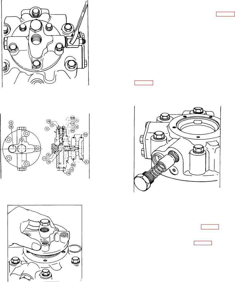
Units no longer In production may have a nonadjustable
high pressure pilot valve spring seat (7B) (See Fig 187).
Remove spring seat (7B) and shim(s) (10), O-ring (12),
spring (11), and valve pilot (13) and proceed to Step 5.
C-4 Remove Inner spring seat (10), O-ring (6), pilot
spring (11), and valve pilot (13).
C-5 Inspect pilot valve seat (16) If damaged, replace
body assembly (5) Do not attempt to remove valve seat
(16) from valve body (5).
C-6 Remove 3 hex bolts (50), 2 hex bolts (48), and 5
lock washers (47). Lift valve body (5) from motor cover
(4) See Fig 188.
C-7 Remove O-ring (46), back-up rings (51), and O-rings
Figure 186.
(52).
Removing high pressure pilot valve
Figure 187.
Phase III non-adjustable high pressure
Figure 189.
relief valve
Removing low pressure relief valve
MOTOR DISASSEMBLY
1. Remove low pressure relief valve plug (73) O-ring
(17), spring (62), and plunger (61). See Fig 189.
2. Remove shuttle valve plugs (35) and O-rings (17).
Slide shuttle (32) from cover (4) See Fig 190.
NOTE:
Spring centering shuttle plugs (29) and O-ring (17)
should be removed as an assembly Plug (28) spring
(30), and plunger (31) should not be removed from plug
(29) unless damaged. If damaged, remove plug (28)
and slide spring (30) and plunger (31) from plug (29).
3 Unless leakage is experienced, do not remove plugs
Figure 188.
(33) or O-rings (34) If leaking, replace O-rings(34).
Removing high pressure relief valve body
116