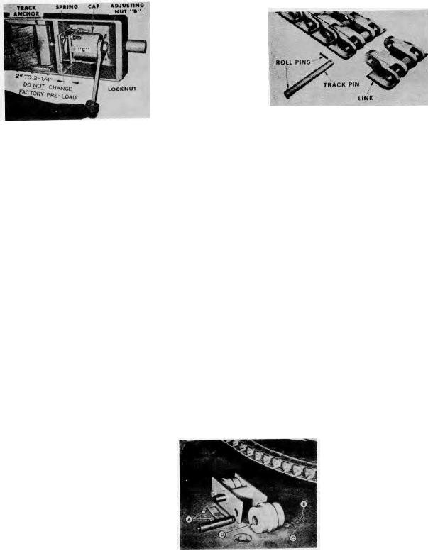
Track Tension Adjustment (Factory assembly view)
Track Link and Pin Detail
Figure 3
Figure 4
CAUTION! Always take the proper precautions when making such an adjustment where parts are subjected
to strong
spring tension.
Replacing Crawler Track Assembly
(1) Removing Crawler Assembly: (Figure 4)
a. Elevate paver to allow adequate working area under the hopper.
b. Release tension on track assembly.
c. Drive the roll pins out of each end of one of the track pins.
d. Drive track pin out of crawler link.
e. Attach a cable to the "broken" track and pull track off track frame.
(2) Replacing Crawler Assembly:
One complete track is shipped in two sections for ease of handling. One section of the track will have one (1)
more link than the other section. Couple these two sections together with track pin for one complete track
assembly.
a. Place blocking of sufficient height on top of track frame to support tracks level with upper roller
assembly.
b. Attach cable to one end of the track assembly and pull tracks over top of track frame until loose
ends of track are under track frame toward the hopper end.
c. Couple the two ends of tracks together with track pin.
d. Drive roll pin into each end of track pin.
e. Adjust track to the recommended tension.
f. Release and remove jacks that elevated paver.
Oscillating Track Roller (Partially dismantled)
Figure 5
Replacing Oscillating Roller Assembly
(Figure 5)
Three sets of oscillating track roller assemblies are part of each track assembly. When bushings and rollers
require replacement, these assemblies can quickly be removed from the track frame by the following
procedures:
IMPORTANT: Operating paver with worn track roller bushings will cause wavy surfaces on the laid mat,
and unsatisfactory transverse joints, erratic depth control and marks on mat when paver stops. (1) Elevate
machine until it is possible to loosen track take-up assembly allowing track to hang free.
(2) Remove the complete oscillating roller assembly by removing the four nuts "A" which hold it to the track
frame.
(3) To further disassemble the rollers from the oscillating assembly, remove bolt and lock, Items "B" and "C."
Then, push shaft through the roller.
Page 100

