
CRAWLER TRACKS
The most expensive mistake the owner of any track type piece of equipment can make is to assume that
such an uncomplicated mechanism as a crawler track needs no care. An effective service life is built into the
track, but without proper care its life will be shortened.
The track, rollers, sprockets and take up idlers should be inspected at least once a week. Lubrication should
be according to recommendations. Everytime the paver is cleaned, the track should be sprayed with fuel oil.
There is enough lubricant in the fuel oil to keep the track pins from rusting and binding.
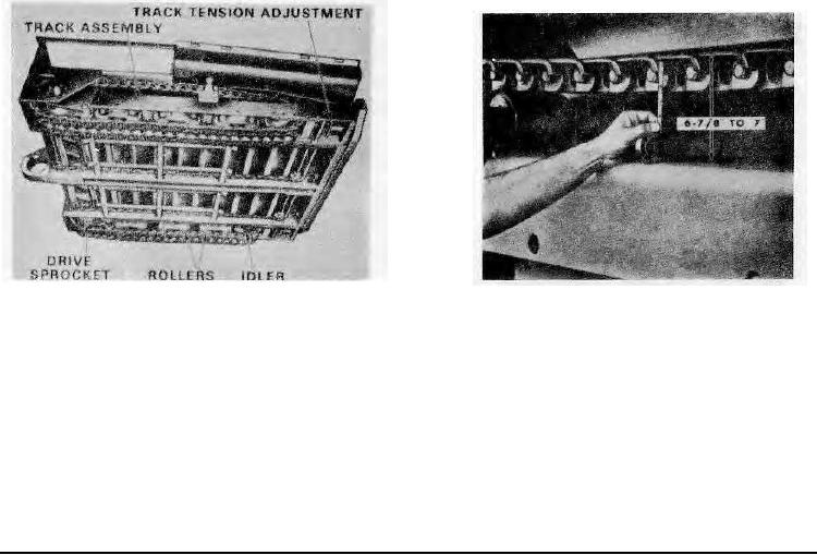
Track tension is most important. The tension de- termination method shown in Figure 2 is a guide. Proper
track tension depends on the type of laying operation. When the base is sandy there tends to be a buildup
on the track bushings. This material will pack and the track tension will increase. The drive sprocket will jump in
the track and cause excessive strain on the rear track sprocket bearings and front idler bearings.
If the tracks are too tight, there is unnecessary strain on the drive assembly and the engine will lug excessively,
and fuel consumption will be high.
A very loose track has a tendency to come off when the machine pivots or backs up an incline. Even if it
does not come off a loose track still may cause wear on the rollers, sprocket teeth and track. Loose track will
tend to whip at travel speeds, which will cause severe impact loads on all running gear parts and allow
additional movement of the contacting surfaces, which consequently increases wear to all parts.
IMPORTANT! A new paver or one having a new set of tracks will require daily tightening of the tracks until all
link pins have "worn in" and stretching of the track no longer occurs. When this initial stretching stops it will only
be necessary to check and tighten the tracks occasionally.
Method of Adjusting Track Tension:
1. Drive the paver to a point where the front end overhangs the track support surface enough to allow the
movement of a long handled wrench engaging the track adjusting Nut "B" on each side of the paver (See
Figure 3).
2. Loosen the locknut and turn Adjusting Nut "B" in the normal way to tighten or loosen.
Bottom View of Tractor Assembly
Measuring Track. Tension
Figure 1
Figure 2
3. Take a measurement of the sag in each track (See Figure 2) and adjust the tension accordingly to arrive
at the 67/g" dimension shown. Be sure to measure at the lowest point of track sag.
4. Tighten the locknuts after making an adjustment.
Tension Pre-load:
A minimum tension on the track is set at the factory by adjustment of the "pre-load". The spring is partly
compressed by the Cap which is drawn to within 2" or 24" of the Base Plate (See Figure 3) by adjustment of
the stud Hex Nuts
"C". This Portion of the tension assembly requires no further adjustment! If a spring or other parts are
replaced, adjust the Pre-load to this specified dimension.
Page 99