
TM 5-3895-385-23-3
0441
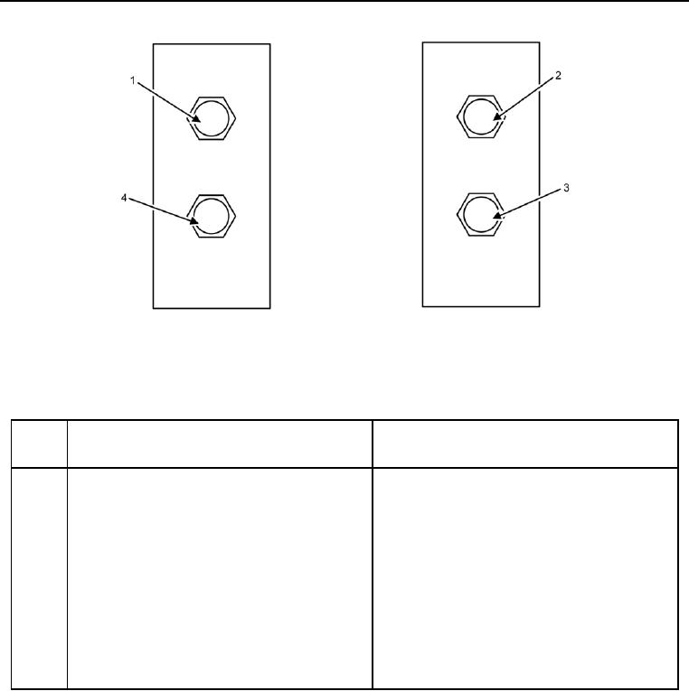
Figure 21. Left and Right Screed Lift Cylinder Bulkheads (View from Engine).
Table 21. Left and Right Screed Lift Cylinder Bulkheads (View from Engine).
ITEM
NO.
ITEM DESCRIPTION
DESTINATION
1
Hose 36 is connected to bulkhead connector 1.
Hose 36 is connected to screed lift cylinder tee,
which is connected to hose 37 which is
connected to ST on Main Hydraulic Manifold
(Figure 3, Item 27).
2
Screed lift cylinder tee and hose 37 are
Hose 37 is connected to ST on Main Hydraulic
connected to bulkhead connector 2.
Manifold (Figure 3, Item 27).
3
Hose 40 is connected to bulkhead connector 3
Hose 40 is connected to S2 on Main Hydraulic
Manifold (Figure 3, Item 29).
4
.Hose 39 is connected to bulkhead connector 4.
Hose 39 is connected to S1 on Main Hydraulic
Manifold (Figure 3, Item 28).