
TM 5-3895-385-23-3
0441
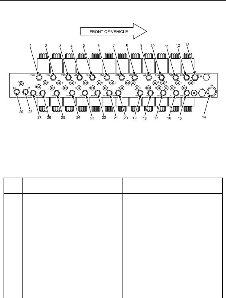
Figure 3. Main Hydraulic Manifold Right Side.
Table 3. Main Hydraulic Manifold Right Side.
ITEM
NO.
ITEM DESCRIPTION
DESTINATION
1
PCB is power crown motor to crown. Hose 72B
Hose 72B is connected to bulkhead connector
is connected to PCB.
26 (Figures 22 and 23, Item 26).
2
THB is truck hitch cylinder extend. Hose 123B is
Hose 123B is connected to bulkhead connector
connected to THB.
(truck hitch cylinder extend), which is connected
to hose 124B, which is connected to the extend
side of truck hitch cylinder.
3
RSB is right side screed slope cylinder retract.
Hose 29B is connected to bulkhead connector 9
Hose 29B is connected to RSB.
(Figures 22 and 23, Item 9).
4
LSB is left side screed slope cylinder retract.
Hose 38B is connected to bulkhead connector 2
Hose 38B is connected to LSB.
(Figures 22 and 23, Item 2).
5
REB is right side screed extension cylinder
Hose 35B is connected to bulkhead connector
retract. Hose 35B is connected to REB.
29 (Figures 22 and 23, Item 29).
6
RCB is right cutoff cylinder extend. Hose 55B is
Hose 55B is connected to bulkhead connector
connected to RCB.
10 (Figures 22 and 23, Item 10).