
TM 5-3895-385-23-2
0370
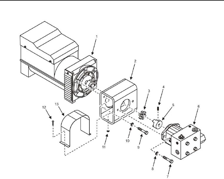
Flow Control Assembly Removal
Figure 6. Hydraulic Generator Motor and Flow Control Assembly.
1. Remove hydraulic generator (perform steps 1 9 of Hydraulic Generator Removal task).
2. Remove two screws (Figure 6, Item 12), nuts (Figure 6, Item 11), and coupling cover (Figure 6, Item 13) from
motor mount (Figure 6, Item 2).
3. Remove four bolts (Figure 6, Item 9), lock washers (Figure 6, Item 10), and motor mount (Figure 6, Item 2)
from hydraulic generator (Figure 6, Item 1). Discard lock washers.
4. Remove two bolts (Figure 6, Item 7), lock washers (Figure 6, Item 8), and flow control assembly (Figure 6,
Item 6) from motor mount (Figure 6, Item 2). Discard lock washers.
5. Remove setscrew (Figure 6, Item 4), coupler (Figure 6, Item 5), and coupling insert (Figure 6, Item 3) from
flow control assembly (Figure 6, Item 6).
END OF TASK