
TM 5-3895-385-23-2
0337
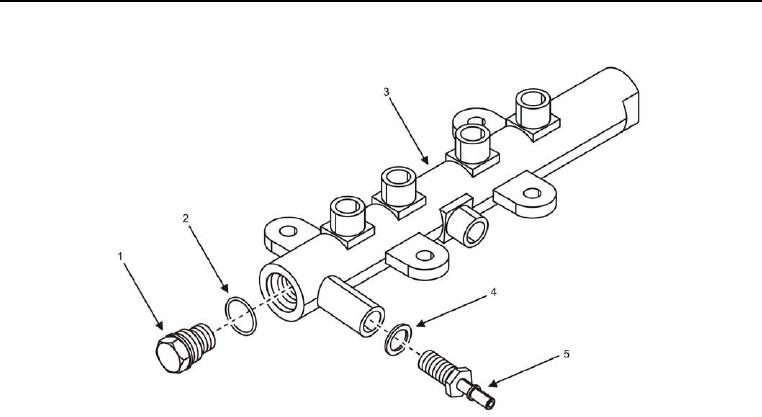
Fuel Pressure Relief Valve Replacement
Figure 4. Fuel Pressure Relief Valve -- Removal.
NOTE
Clean the area around the fuel pressure relief valve with wiping rag prior to performing any
repair steps.
Place wiping rag under fuel pressure relief valve to capture spilled fuel when fuel lines are
removed.
The O-ring is part of the fuel pressure relief valve. The O-ring may or may not remain
attached to the fuel pressure relief valve upon removal.
1. Remove fuel pressure relief valve (Figure 4, Item 1) and O-ring (Figure 4, Item 2) from fuel rail (Figure 4, Item
3). Discard fuel pressure relief valve and O-ring.
2. Cap/plug fuel pressure relief valve (Figure 4, Item 1) port on fuel rail (Figure 2, Item 3).
3. Remove quick disconnect connector (Figure 4, Item 5) and washer (Figure 4, Item 4) from fuel rail (Figure 4,
Item 3). Discard washer.
4. Install new O-ring (Figure 4, Item 2) onto fuel pressure relief valve (Figure 4, Item 1).
CAUTION
Over-tightening the fuel pressure relief valve can cause fuel leaks. Secure the fuel pressure relief
valve to the proper torque specification. Failure to comply may cause damage to equipment.
5. Remove cap/plug, and install fuel pressure relief valve (Figure 4, Item 1) into fuel rail (Figure 4, Item 3), and
torque to 74 ft-lb (100 Nm).
6. Install quick disconnect connector (Figure 4, Item 5) and new washer (Figure 4, Item 4) into fuel rail (Figure 4,
Item 3).
END OF TASK