TM 5-3895-385-23-2
0311
Screed Vibrator Hydraulic Solenoid Coil Removal
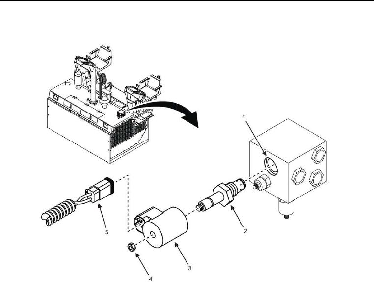
Figure 1. Screed Vibrator Hydraulic Solenoid Coil.
1. Open left floorboard access panel.
2. Remove W1 J22 (Figure 1, Item 5) from screed vibrator hydraulic solenoid coil (Figure 1, Item 3).
3. Remove nut (Figure 1, Item 4), screed vibrator hydraulic solenoid coil (Figure 1, Item 3), and 2-way poppet
(Figure 1, Item 2) from vibrator/blower manifold (Figure 1, Item 1).
END OF TASK
Screed Vibrator Hydraulic Solenoid Coil Installation
1. Install nut (Figure 1, Item 4), screed vibrator hydraulic solenoid coil (Figure 1, Item 3), and 2-way poppet
(Figure 1, Item 2) onto vibrator/blower manifold (Figure 1, Item 1).
2. Install W1 J22 (Figure 1, Item 5) to screed vibrator hydraulic solenoid coil (Figure 1, Item 3).
3. Close left floorboard access panel.
END OF TASK

