
TM 5-3895-385-23-2
0303
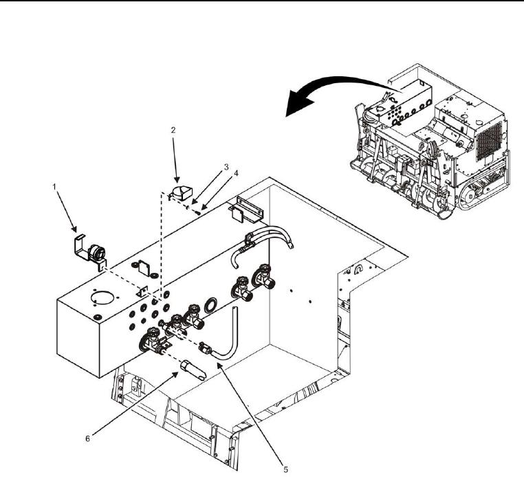
Hydraulic Tank Removal -- Continued.
Figure 2. Hydraulic Tank Hoses -- Removal.
3. Remove bolt (Figure 2, Item 4), lock washer (Figure 2, Item 3), horn (Figure 2, Item 2), and backup alarm
(Figure 2, Item 1) from hydraulic tank. Discard lock washer.
4. Disconnect W1 J20 (Figure 2, Item 5) from hydraulic temperature sensor.
CAUTION
Tag and label hydraulic hoses prior to removal. Hydraulic hoses must be installed correctly for
proper operation. Failure to comply may cause damage to equipment.
5. Close five valves and disconnect five hydraulic hoses (Figure 2, Item 6) from valves, and cap/plug hydraulic
hoses.