TM 5-3895-385-23-2
0260
Hopper Front Hydraulic Cylinder Installation -- Continued.
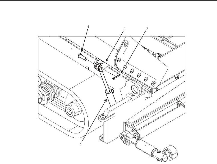
Figure 12. Hopper Front Hydraulic Cylinder -- Installation.
4. Install clevis pin (Figure 12, Item 1), new cotter pin (Figure 12, Item 3), and hopper front hydraulic cylinder
(Figure 12, Item 4) onto top bracket (Figure 12, Item 2).
END OF TASK
FOLLOW-ON TASK
1. Remove lifting device.
2. Set BATTERY DISCONNECT switch to ON (TM 5-3895-385-10).
3. Verify proper operation.
4. Dispose of hydraulic oil and wiping rags In Accordance With (IAW) local Standard Operating Procedure
(SOP).
END OF TASK
END OF WORK PACKAGE

