
TM 5-3895-385-23-2
0256
Power Crown Hydraulic Motor Removal -- Continued.
2. Remove two bolts (Figure 1, Items 5 and 7), lock washers (Figure 1, Items 4 and 8), and flat washers (Figure
1, Items 3 and 9) from power crown hydraulic motor (Figure 1, Item 2). Discard lock washers.
3. Remove power crown roller chain (Figure 1, Item 10) from sprocket on power crown hydraulic motor (Figure
1, Item 2), and remove power crown hydraulic motor (Figure 1, Item 2) from power crown plate (Figure 1, Item
1).
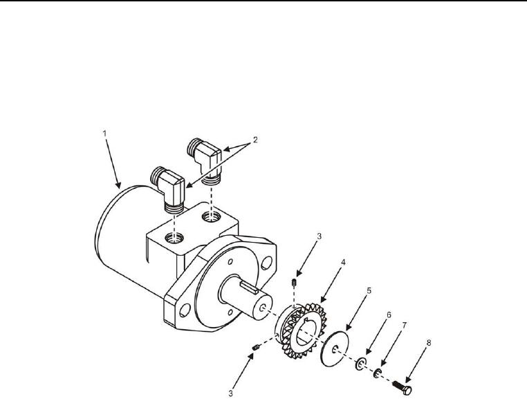
Figure 2. Power Crown Hydraulic Motor Fittings.
4. Remove bolt (Figure 2, Item 8), lock washer (Figure 2, Item 7), and two flat washers (Figure 2, Items 5 and 6)
from power crown hydraulic motor (Figure 2, Item 1). Discard lock washer.
5. Remove two set screws (Figure 2, Item 3) and sprocket (Figure 2, Item 4) from power crown hydraulic motor
(Figure 2, Item 1).
6. Remove hydraulic fittings (Figure 2, Item 2) from power crown hydraulic motor (Figure 2, Item 1).
END OF TASK
Power Crown Hydraulic Motor Installation
1. Install hydraulic fittings (Figure 2, Item 2) onto power crown hydraulic motor (Figure 2, Item 1).
2. Install sprocket (Figure 2, Item 4) onto power crown hydraulic motor (Figure 2, Item 1).
3. Install bolt (Figure 2, Item 8), new lock washer (Figure 2, Item 7), and two flat washers (Figure 2, Items 5 and
6) onto power crown hydraulic motor (Figure 2, Item 1).
4. Install two set screws (Figure 2, Item 3) onto sprocket (Figure 2, Item 4).