TM 5-3895-373-34
A.
REMOVE - Continued.
7.
REMOVE AUGER/CONVEYOR SPEED CONTROL
VALVE.
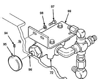
NOTE
Removal procedures for both the left
and
right
auger/conveyor
speed
control valve are the same. The
illustrations in this procedure are for
the
right
auger/conveyor
speed
control valve. The fittings may be
positioned slightly different for the
left speed control valve.
a.
Loosen set screw (94) on knob (95). Remove
knob from adjustment screw (96).
b.
Remove bolts (97) and sleeve spacers (98)
from mounting bracket (99) and remove
auger/conveyor speed control valve (72).
Install knob (95) back onto adjustment screw
(96)
and
tighten
set
screw
(94).
NOTE:
RIGHT AUGER/CONVEYOR SPEED
CONTROL VALVE SHOWN.
GO TO NEXT PAGE
2-747