TM 5-3895-373-34
E.
ASSEMBLE Continued.
r.
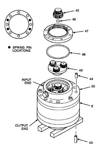
Using 3/8 in. drive pin punch, drive shortest
spring pins (44) to seat in mating holes at top of
speed reduction gearbox (8). Leave about 1/2
in. of spring pin exposed. Refer to inset view for
location of spring pin bores.
s.
Turn speed reduction gearbox (8) on its side.
Using 3/8 in. drive pin punch, drive longest
spring pins (43) into mating holes on output end
of gearbox. Drive spring pins until trailing ends
are seated about 3/8 in. (10 mm) deep in
gearbox.
t.
Stand speed reduction gearbox (8) on cribbing,
input housing (50) up. Install speed reducer
gearset (49).
u.
Press thrust washer bearing (46) into mating
bore of spur gear (45).
v.
Align and install spur gear (45) in center of
installed speed reducer gearset (49).
w.
Lubricate o-ring (48) with petrolatum. Install o-
ring on bottom side of internal gear (47).
x.
With mounting holes aligned, seat internal gear
(47) on installed input housing (50).
GO TO NEXT PAGE
2-487

