TM 5-3895-373-34
E.
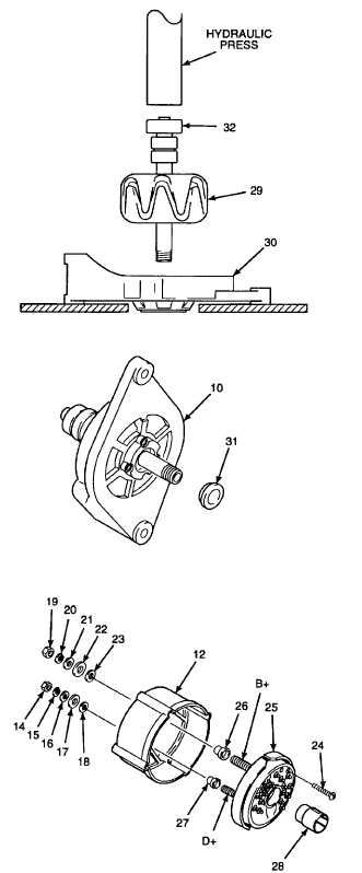
ASSEMBLE - Continued.
2.
USE
HOLLOW
SPACER
FROM
UNIVERSAL
PULLER KIT AND HYDRAULIC PRESS FRAME TO
PRESS BEARING (32) ONTO ROTOR (29) AS FAR AS
IT WILL GO.
3.
INSTALL
ROTOR,
SEAL,
AND
ELECTRICAL
COVER INTO DRIVE END BELL.
a.
Place drive end bell (30), inside face up, on
hydraulic press frame.
b.
Press shaft of rotor (29) into drive end bell (30)
bearing as far as it will go.
c.
Remove assembled rotor and drive end bell (10)
from hydraulic press frame.
d.
Install seal (31) bevel-end down. Seat seal by
pressing gently, moving around the seal surface,
with a straight punch.
4.
INSTALL RECTIFER INTO COLLECTOR RING
END SHIELD.
a. Thread insulated bushing (27) onto small (D+)
terminal of rectifier (25)
b.
Install insulated bushing (26) onto large (B+)
terminal of rectifier (25).
c.
Install rectifier (25) and screws (24) into collector
ring end shield (12). Terminals B+ and D+ must
extend through collector ring end shield (12) with
insulated bushings fully seated in holes. Tighten
screws to 15 lb-in (1, 7 N.m).
d.
Install small fibre washer (23), large fibre
washers (22), flat washer (21), lockwasher (20),
and hex nut (19) onto large (B+) terminal.
Tighten hex nut finger tight.
e.
Install small fibre washer (18) large fibre washer
(17), flat washer (16), lockwasher (15), and hex
nut (14) onto small (D+) terminal. Tighten hex
nut finger tight.
GO TO NEXT PAGE
2-333


