TM 5-3895-373-34
2.24.
REPAIR ALTERNATOR - Continued
A.
DISASSEMBLE - Continued.
9.
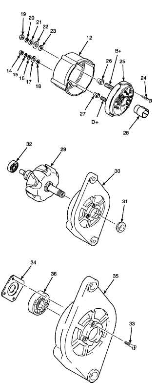
REMOVE RECTIFIER AND ELECTRICAL COVER
FROM COLLECTOR RING END SHIELD.
a.
Remove hex nut (14), lockwasher (15), flat
washer (16), large fibre washer (17) and small
fibre washer (18) from D+ terminal of collector
ring end shield (12). Discard lockwasher.
b.
Remove hex nut (19), lockwasher (20), flat
washer (21), large fibre washer (22), and small
fiber washer (23) from B+ terminal. Discard
lockwasher.
c.
Remove screws (24) and rectifier (25) from
collector ring end shield (12).
d.
Pull insulated bushing (26) from large (B+)
terminal of rectifier (25Unthread insulated
bushing (27) from small (D+) terminal of
rectifier.
e.
Remove electrical cover (28).
10.
REMOVE ROTOR AND SEAL FROM DRIVE END
BELL.
a.
Remove rotor (29) from drive end bell (30).
b.
If rotor cannot be removed from drive end bell
by hand, use a bearing puller from the
universal puller kit to press rotor from drive
end bell (30).
c.
Remove seal (31).
d.
Use a bearing puller from universal puller kit to
remove bearing (32) from rotor.
11.
REMOVE BEARING FROM DRIVE END BELL.
a.
Remove screws (33).
b.
Remove retaining plate (34) from inside of
drive end bell (35).
c.
Slide bearing (36) from inside of drive end bell.
GO TO NEXT PAGE
2-328


