TM 5-3895-373-34
1.21
50/50 FLOW DIVIDER.
50/50 flow dividers split the flow from a single input into
two equal output flows. There are two types of 50/50
flow divider used in the paving machine.
a.
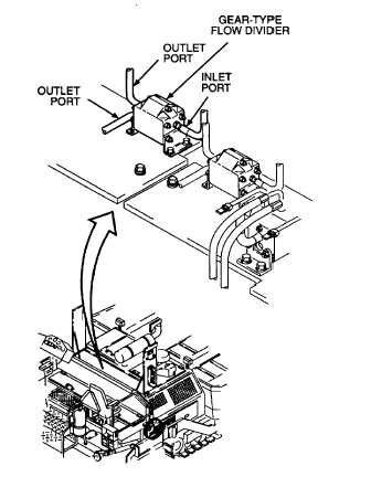
Gear-type flow dividers. Gear-type flow
dividers are mounted on brackets that attach to the valve
panel. There are three gear-type flow dividers in the
paving machine. One flow divider splits the input flow to
the two auger/conveyor systems. A second flow divider
splits flow between the stack valve and the tow point
cylinders. Each displaces 0.32 cubic inches (5,24 ml)
per side. A third flow divider splits flow between two tow
point cylinder circuits and has a displacement of 0.109
cubic inches (1,786 ml) per side. Hydraulic oil enters
the inlet port and passes through two sets of meshing,
double-gear assemblies. Each double gear assembly
consists of two gears joined by a single shaft. As oil
passes over the gears, they turn and engage an opposite
set of gears. Hydraulic oil flow is equally regulated by
the inertia created by the meshing sets of gears.
Hydraulic oil output is equal from both outlet ports.
b.
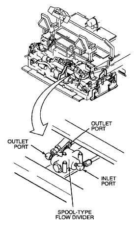
Spool-type flow dividers. Spool-type flow
dividers contain a pressure-compensated spool that
balances oil flow. There is one spool-type flow divider
located in the screed vibrator assembly. The flow divider
input is channeled through a bored spool. The spool
centers and self-adjusts as the oil passes through. This
compensates for unequal hydraulic oil draw from each of
the components and ensures an equal and constant
output flow.
1-12


