TM 5-3895-373-34
1.22
CONTROL HANDLES.
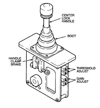
Two control handles (joysticks) are located on the
operator console. Each control handle is a friction held,
bi-directional unit with adjustable drag. A clamp-type
brake holds each handle at set position. Each handle
has a throw of 30° on either side of center. Control
handles operate on a 12 volt DC current. A printed
circuit board on each handle subassembly converts the
12 volts DC to a 96 mA signal to power the coils on
pump pilot control valves. Full current output, with the
control handles at 30°, is a maximum of 2 amps into a 5
ohm load. Step current (96 mA) is a maximum of 50% of
full current output. The current can be adjusted through
the use of threshold and gain controls. Control handles
govern startup functions, travel speed variations, brake
release (when engaging paving machine travel), and
automatic screed vibration operation. The paving
machine engine will not start unless both control handles
are centered. Each control handle operates its
respective track. When paving with screed vibration in
automatic, screed vibration is halted when either control
handle is centered. Screed vibration resumes when both
handles are moved out of the center position.
1.23
HIGH SPEED SHIFT VALVE.
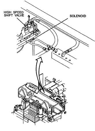
The high speed shift valve is a 12 volt DC, solenoid
activated, two-position, four-way valve that enables the
paving machine to move at two separate speed ranges.
The high speed is used for traveling, and the low speed
is used for paving. The solenoid is wet-operated for low
impact and smooth operation. The high speed shift
valve controls oil flow to the hydraulic motor control
pistons. The oil flow determines the control piston angle,
which determines drive speed. The internal charge
circuit of the left propulsion pump provides the required
flow of hydraulic oil to the high speed shift valve.
1-13


