TM 5-3895-373-20
7.8.
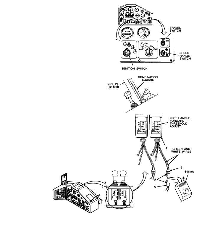
ADJUST/CALIBRATE CONTROL HANDLES - Continued.
A.
CALIBRATE Continued.
b.
Turn ignition switch to the ON position. Refer to
TM 5-3895-373-10.
c.
Set speed range switch to the down, "tortoise"
pave position. Refer to TM 5-3895-373-10.
d.
Set travel switch to the up, forward/reverse "F/R"
position. Refer to TM 5-3895-373-10.
e.
Disconnect electrical connector P31 (3) (green
and white wires) on the left control handle (4)
from electrical connector J31 (5).
f.
Set digital multimeter for mA DC reading.
g.
Insert
digital
multimeter
positive
lead
into
terminal A on electrical connector P31 (3).
h.
Insert digital multimeter negative lead into
terminal A on electrical connector J31 (5).
i.
Move left control handle (4) 0.75 in. (19 mm)
from
neutral
to
forward
position.
Use
a
combination square and the top of the handle as
references.
j.
Digital multimeter should read 6 to 8 mA.
NOTE
The forward threshold potentiometer
(FT)
and
the
maximum
forward
threshold potentiometer interact on each
other.
An
adjustment
to
either
potentiometer will require the other
setting to be checked.
k.
If meter reading is less than 6 mA or greater
than 8 mA, using a jeweler’s screwdriver, adjust
left
control
handle
(4)
forward
threshold
potentiometer (FT) until a reading of 6 to 8 mA is
obtained.
l.
Move left control handle (4) to full forward
position.
GO TO NEXT PAGE
7-68