TM 5-3895-373-20
A.
REMOVE - Continued.
3.
REMOVE VIBRATION MOTOR.
NOTE
The following removal procedure applies
to the main screed vibration motor and
the extension screed vibration motors.
NOTE
There is not enough clearance to remove
hex head cap screws when vibration
motor is flush against motor mount.
Loosen cap screws evenly while sliding
vibration motor away from motor mount.
a.
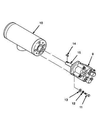
Slide vibration motor (9) away from motor
mount (10) while loosening hex head cap
screws (11). Use a crowfoot wrench on cap
screws if necessary.
b.
Remove hex head cap screws (11),
lockwashers (12), and flat washers (13).
Discard lockwashers.
c.
Remove vibration motor (9) and shaft key (14)
from vibration motor drive shaft (15). Tape
shaft key back onto vibration motor drive
shaft.
B.
INSTALL.
1.
INSTALL VIBRATION MOTOR.
Elbows on the main and extension screed
vibration motors are orientated
differently. Ensure each motor is
installed in the correct location and at the
same orientation as removed or hydraulic
tube connection for the vibration motors
will not be possible.
NOTE
The following installation procedure
applies to the main screed vibration
motor and the extension screed vibration
motor.
a.
Remove tape and shaft key (14) from vibration
motor drive shaft (15).
GO TO NEXT PAGE
15-89